OTN – Lesson 6 – Converting OTL3.4 Back into OTU3 – Video 2

This blog post contains a video that serves as the 2nd of two videos that describe the functionality of the OTL3.4 Sink Terminal (aka the OTSiG/OTUk_A_Sk Atomic Function). This video focuses on Skew Compensation and ultimately combining the 4 OTL3.4 Lanes back into a Composite OTU3 signal.

OTN – Lesson 6 – Converting OTL3.4 Signals back into a Composite OTU3 Signal – Video 2 of 2

This blog post contains the second (of 2) videos that describes how we take an OTL3.4 Interface (or set of signals) and convert these signals back into a single (composite) OTU3 signal.  

This particular video completes the discussion of the OTSiG/OTUk_A_Sk Atomic Function (which, again, is a fancy word for OTL3.4 Sink Terminal).  

NOTE:  We formally introduce the OTSiG/OTUk_A_Sk Atomic Function in Lesson 9.  

This video discusses how the Lane Marker and Delay Processing Block (within the OTSiG/OTUk_A_Sk Function) evaluates all of the data and metrics coming from the four Lane Frame Alignment, Lane Alignment Recovery, and Elastic Store blocks and:

  • Measures and performs Skew Compensation,
  • Declares the dLOL (Loss of Lane Alignment) Defect Condition and 
  • Routes the de-skewed data to the 16-Byte Block MUX – which combines each of the four OTL3.4 lane signals back into a composite OTU3 signal. 

Continue reading “OTN – Lesson 6 – Converting OTL3.4 Back into OTU3 – Video 2”

OTN – Lesson 7 – Converting OTL4.4 Back into an OTU4 Signal – Video 3

This post presents both information and video training on how we take an OTL4.4 signal and recombine it back into a composite OTU4 signal. This post serves as the third of 3 videos for the OTL4.4 Sink Terminal.

In this video we focus on the Lane Alignment Recovery Block and Skew Compensation.

OTN – Lesson 7 – Converting OTL4.4 Signals back into a Composite OTU4 Signal – Video 3

This blog post presents the 3rd (of a set of 3 videos) that discusses how we convert an OTL4.4 Interface (or group of signals) back into a single (composite) OTU4 signal.  

In particular, this video discusses the following:

  • It outlines how the OTSiG/OTUk_A_Sk function declares and clears the dLOR (Loss of Recovery) defect condition, for each of the 20 Logical Lanes, by walking through the Lane Alignment Recovery Block – LOR/OOR/IR State Machine diagram.  
  • This video also discusses Lane-to-Lane Skew Compensation, and
  • How the OTSiG/OTUk_A_Sk function declares or clears the dLOL defect condition, and 
  • How the OTSiG/OTUk_A_Sk function combines the 20 Logical Lanes back into a single (composite) OTU4 signal.  

Continue reading “OTN – Lesson 7 – Converting OTL4.4 Back into an OTU4 Signal – Video 3”

OTN – Lesson 9 – Video 11 – OTU Layer Defect Handling Requirements and Scenarios

In this video, we presume that some OTUk-Layer circuitry is declaring a certain defect condition. We then determine how OTU (and in some cases) ODU-layer circuitry is expected to respond.

OTN – Lesson 9 – Video 11 – OTU Layer Defect Scenarios

This blog post presents a video that discusses the various defects that OTN equipment can declare at the OTU Layer.  Additionally, this video will describe how OTU Layer circuitry should respond to and handle these defect conditions.  

This video will state whether OTU Layer circuitry should:

  • Transmit the SM-BDI Indicator upstream, or 
  • Transmit the ODU-AIS Maintenance Signal downstream, 
  • Increment Certain Performance Monitoring parameters, or
  • Halt Incrementing Certain Performance Monitoring parameters.

In response to each type of defect that OTU Layer circuitry can declare.

This video covers both Single-Lane (e.g., OTSi/OTUk_A_Sk) and Multi-Lane (e.g., OTSiG/OTUk_A_Sk) applications. 

Continue reading “OTN – Lesson 9 – Video 11 – OTU Layer Defect Handling Requirements and Scenarios”

What is Defect Correlation?

This post briefly defines and explains what Defect Correlation means. In short, the Defect Correlation equations will specify how we expect a system to respond to a specific defect condition.

What is Defect Correlation, and How Should You Interpret It?

The purpose of this blog post is two-fold.

  • To describe the concept of Defect Correlation and
  • To discuss how to interpret the meaning of Defect Correlation and their Equations.

Introduction

Numerous ITU Standards (such as ITU-T G.798 for OTN applications) will define various aspects of defects. These standards will define a defect, such as dLOS (the Loss of Signal) and dLOF (the Loss of Frame).

These standards will (sometimes) describe the conditions that an OTN Network Element (be it an STE or PTE) should use to declare or clear a given defect.

For instance, ITU-T G.798 specifies all of the following defects that an OTN STE can declare and clear.

(*) – Requires membership to THE BEST DARN OTN TRAINING PRESENTATION…PERIOD!!! to see these links.  

And it is excellent that the ITU-T standard committee does this for us.

But let’s now take a closer look at these defects from a System-Level standpoint.

Should One Defect Lead to Many Other Defects?

Suppose an OTN STE declares the dLOS-P (Loss of Signal-Path) defect condition with its incoming optical lanes or signal.

This STE will declare the dLOS-P condition for one of two reasons.

  1.  Because the optical components (upstream) are detecting too little optical signal energy (within the incoming signal) or
  2. the Clock and Data Recovery circuitry (within the STE electronics) is detecting an absence of recovered (data) signal activity for an extended period.

In Figure 1, I illustrate the OTSi/OTUk-a_A_Sk function, declaring the dLOS-P defect.
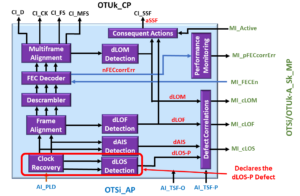
OTSi/OTUk-a_A_Sk Function declares dLOS Defect - Defect Correlation

Figure 1, The OTSi/OTUk-a_A_Sk Atomic Function, declares the dLOS Defect Condition.  

In either of these cases, it is clear that this OTN STE should declare the dLOS-P defect condition.

How about the dLOF Condition?

However, if that same OTN STE is not receiving any discernable signal from the remote STE, it is safe to say that it will not be receiving the FAS fields (within this now non-existent incoming data stream).

Should this OTN STE also declare the dLOF defect as well?

In Figure 2, I illustrate the OTSi/OTUk-a_A_Sk function, declaring the dLOF defect condition and the dLOS-P defect condition.

OTSi/OTUk-a_A_Sk Function Declares both the dLOS and dLOF Defects

Figure 2, The OTSi/OTUk-a_A_Sk function declaring the dLOF and dLOS-P Defect Conditions

Clueless about OTN? We Can Help!! Click on the Banner Below to Learn More!!!

Corporate Discounts Available!!!

What about the dLOM Condition?

And since the OTN STE is not receiving any FAS field bytes, it cannot locate the MFAS bytes.

Should this OTN STE also declare the dLOM defect too?

In Figure 3, I illustrate the OTSi/OTUk-a_A_Sk function, declaring the dLOM, dLOF, and dLOS-P Defect conditions.

OTSi/OTUk-a_A_Sk Function declares dLOS-P, dLOF and dLOM Defects

Figure 3, The OTSi/OTUk-a_A_Sk Atomic Function declaring the dLOM, dLOF, and dLOS-P Defect Conditions

How about the dTIM Condition?

Finally, since our OTN STE is not receiving any discernable signal (from the remote STE), and it cannot locate the boundaries of each incoming OTUk frame, it will certainly not obtain a Trail Trace Identification Message that matches that of the “Expected Trail Trace Identification” Message.

Should this OTN STE also declare the dTIM defect as well?

In Figure 4, I illustrate the OTUk_TT_Sk function declaring the dTIM defect, while the upstream OTSi/OTUk-a_A_Sk function reports the dLOS-P, dLOF, and dLOM defect conditions.

OTUk_TT_Sk Function declares dTIM defect - due to No Defect Correlation

Figure 4, The OTUk_TT_Sk Atomic Function (downstream from the OTSi/OTUk-a_A_Sk Function) declares the dTIM defect.

Many Defects, all due to the dLOS-P Condition

In this scenario, a Loss of Signal event would cause the OTN STE to declare the dLOS, dLOF, dLOM, and dTIM defect conditions.

The OTN STE will accurately declare all four defect conditions because conditions warrant that the STE declare each of these defects.

However, allowing an STE to declare multiple defects (e.g., dLOS, dLOF, dLOM, and dTIM) can be confusing to both System-Management and the System Operator.

Confused Guy - Too Many Defects

I could take this exercise even further and include some of the PTE/ODUk-related defects that an OTN PTE would declare (e.g., ODUk-AIS), all because of the dLOS-P condition. But I think that you get my point.

Whenever a service-affecting defect occurs, the OTN STE needs to alert System Management of a concise description of the problem (just dLOS-P in this case).

The intent should be to help the System Operator isolate the root cause of these problems.

We should not be bombarding the System Operator with a whole slew of defects, which are just artifacts of a single defect.

If the OTN STE declares the dTIM, dLOM, dLOF, and dLOS-P defects, the root cause of this problem has nothing to do with a mismatch in the Trail-Trace Identification Message.

Hence the Purpose of Defect Correlation

The purpose of Defect Correlation and Defect Correlation equations is to establish and report ONLY the root cause of problems to System Management.

The Defect Correlation Equations accomplishes this by creating a hierarchy of defects.

I’ll explain this.

Let’s list some Defect Correlation Equations for the OTSi/OTUk_A_Sk and OTUk_TT_Sk Atomic Functions.

For the OTSi/OTUk_A_Sk Atomic Function

The OTSi/OTUk_A_Sk function has the following Defect Correlation equations:

  • cLOS-P ⇐ dLOS-P and (NOT AI_TSF-P)
  • cLOF ⇐ dLOF and (NOT dLOS-P) and (NOT dAIS) and (NOT AI_TSF-P)
  • cLOM ⇐ dLOM and (NOT dLOS-P) and (NOT dLOF) and (NOT dAIS) and (NOT AI_TSF-P)

Let’s also include the following Consequent Equation to bridge the OTUk_TT_Sk function to the OTSi/OTUk_A_Sk function.

aSSF ⇐ dLOS-P or dAIS or dLOF or dLOM or AI_TSF-P

For the OTUk_TT_Sk Function

In this case, we will focus on the Defect Correlation equation that pertains to the dTIM defect condition.

  • cTIM ⇐ dTIM and (NOT CI_SSF) and (NOT dAIS)

So Now Let’s Study some of these Defect Correlation Equations

Let’s start with the first equation for the OTSi/OTUk-a_A_Sk function.

  • cLOS-P ⇐ dLOS-P and (NOT AI_TSF-P)

Where: 

cLOS-P is the correlated defect value of the dLOS-P defect state.

dLOS-P is the current state of the dLOS-P defect condition that the OTSi/OTUk_A_Sk function will declare or clear.

AI_TSF-P is the current state of the AI_TSF-P (Trail Signal Fail – Path Indicator) Input to the OTSi/OTUk-A_Sk function.

In this equation, the parameter that begins with the letter “c” is the correlated defect parameter (or defect) state that we ultimately report to System Management.

This equation states that we should only set the variable cLOS-P to TRUE if dLOS-P is TRUE.

In other words, we should only report the Loss of Signal condition (e.g., setting cLOS-P to TRUE) if the STE circuitry declares the dLOS-P defect (due to a lack of signal activity within the Clock Recovery Block, for example).

This equation also states that we should NOT set cLOS-P to TRUE because the upstream Optical Circuitry is declaring some other defect condition and is then asserting its AI_TSF-P output – towards the OTSi/OTUk_A_Sk function).

I show a TRUTH TABLE for this Defect Correlation Equation below in Table 1.

Table 1, TRUTH TABLE for the Defect Correlation Equation, cLOS-P ⇐ dLOS-P AND (NOT AI_TSF-P)

dLOS-P DefectAI_TSF-P StatecLOS-P StateComment
ClearedFALSE0
DeclaredFALSE1Sets cLOS-P to TRUE, because dLOS-P is declared.
Don't CareTRUE0We set cLOS-P to 0 when AI_TSF-P is TRUE.

Let’s look at another Defect Correlation Equation.

  • cLOF ⇐ dLOF and (NOT dLOS-P) and (NOT dAIS) and (NOT AI_TSF-P)

Where:

cLOF is the correlated value of the dLOF defect state.

dAIS is the current state of the dAIS defect condition within the OTSi/OTUk_A_Sk function.

In this equation, we are stating that we should only set cLOF = TRUE (and report the Loss of Frame condition to System Management) if the STE circuitry declares the dLOF condition.

This equation also states that we should NOT be setting cLOF = TRUE (and report the Loss of Frame Condition to System Management) if:

  • The STE is also declaring the dLOS-P defect, or
  • declaring the dAIS (OTUk-AIS) defect, or
  • If the upstream Optical Components assert the AI_TSF-P input to the OTSi/OTUk_A_Sk function.

If any of the three items (above) are TRUE, then we must set cLOF = FALSE.

I show the TRUTH TABLE for this Defect Correlation Equation below in Table 2.

Table 2, The TRUTH TABLE for the Defect Correlation Equation, cLOF ⇐ dLOF AND (NOT dLOS-P) AND (NOT dAIS) AND (NOT AI_TSF-P)

dLOF Defect ConditiondLOS-P Defect ConditiondAIS Defect ConditionAI_TSF-P StatecLOF StateComments
ClearedClearedClearedFALSECleared
DeclaredClearedClearedFALSEDeclaredWe assert cLOF because we are declaring the dLOF Defect
Don't CareDeclaredClearedFALSEClearedWe set cLOF = 0 whenever dLOS-P is declared.
Don't CareClearedDeclaredFALSEClearedWe set cLOF = 0 whenever dAIS is declared.
Don't CareClearedClearedTRUEClearedWe set cLOF = 0 whenever AI_TSF-P is driven TRUE.

At the risk of “whipping a dead horse,” I will show one more example.

  • cTIM ⇐ dTIM and (NOT CI_SSF) and (NOT dAIS)

Where:

cTIM is the correlated value of the dTIM defect state.

CI_SSF is the current state of the CI_SSF (Server Signal Fail Indicator) input pin to the OTUk_TT_Sk function.

If the STE circuitry declares this defect, this equation states that we must only report the Trail Trace Identifier Mismatch Defect (and set cTIM = TRUE).

This equation also states that we MUST NOT set cTIM = TRUE if any of the following is true.

NOTE:  We have the following Consequent Equation for the CI_SSF signal (from the OTSi/OTUk_A_Sk function).

  • aSSF <- dLOS-P or dAIS or dLOF or dLOM or AI_TSF-P

This equation states that if the upstream OTSi/OTUk_A_Sk function declares any of the following defects, it will set aSSF = TRUE.

  • dLOS-P
  • dAIS (OTUk-AIS)
  • dLOF
  • dLOM, or
  • If the upstream Optical Components assert the AI_TSF-P input to the OTSi/OTUk_A_Sk function.

If aSSF = TRUE, then the OTSi/OTUk_A_Sk function will assert the CI_SSF output signal (towards the OTUk_TT_Sk function).

Finally, we get to the bottom line.

These equations state that the STE MUST NOT set cTIM = TRUE (and MUST NOT report the Trail Trace Identifier Mismatch defect to System Management) if any of the following defect conditions are TRUE.

  • dLOS-P
  • dAIS
  • dLOF
  • dLOM
  • If the AI_TSF-P signal (from the upstream Optical Components) is HIGH.

Summary

I believe that you can see that using Defect Correlation Equations makes Defect Reporting and System-Management MUCH EASIER.

Happy due to Defect Correlation

Has Inflation got You Down? Our Price Discounts Can Help You Fight Inflation and Help You Become an Expert on OTN!! Click on the Banner Below to Learn More!!!

Discounts Available for a Short Time!!

CLICK on the Image below for More OTN Related Blog Posts

OTN Related Blog

OTN Related Topics within this Blog

OTN Related Topics within this Blog General Topics Consequent Equations - What are they and How can you use them? ...

OTUk-Backward Defect Indicator

This post defines and describes the Backward Defect Indicator (dBDI) defect for the OTUk Layer


What is the dBDI (Backward Defect Indicator) defect at the OTUk Layer?

In short, the dBDI (or Backward Defect Indicator) signal is functionally equivalent to the RDI (Remote Defect Indicator) for OTN applications.

In OTN applications, Network Equipment can declare the dBDI defect at either the OTUk Layer or the ODUk Layer.

This post will discuss the dBDI defect for the OTUk Layer, which we can call the OTUk-BDI defect condition.

We address the dBDI defect for the ODUk Layer in another post.

In another post, I’ve also described the RDI (Remote Defect Indicator) signal or defect in generic terms.

In this post, we are going to describe the following items.

  • What conditions will cause an OTUk Network Element to transmit the dBDI indicator to the remote Network Element?
  • How does the OTUk Network Element transmit the dBDI indicator to the remote Network Equipment?
  • How does the OTUk Network Element receiving the dBDI signal detect and declare the dBDI defect condition?
  • And, how does the OTUk Network Element clear the dBDI defect condition?

Has Inflation got You Down? Our Price Discounts Can Help You Beat Inflation and Help You Become an Expert on OTN!!! Click on the Banner Below to Learn More!!

Corporate Discounts Available!!

What conditions will cause an OTUk Network Element to transmit the dBDI indicator?

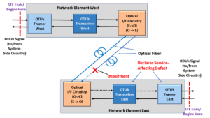
In Figure 1, we illustrate two Network Elements (consisting of OTUk Framers and OTUk Transceivers) exchanging OTUk traffic over Optical Fiber.

We will call one of these Network Elements NETWORK ELEMENT WEST and the other Network Element, NETWORK ELEMENT EAST.

NETWORK ELEMENT WEST contains the following pieces of hardware

  • OTUk Framer West
  • OTUk Transceiver East and
  • Optical I/F Circuitry (O->E)/(E->O)

Likewise, NETWORK ELEMENT EAST contains the following pieces of hardware.

  • OTUk Framer East
  • OTUk Transceiver East and
  • Optical I/F Circuitry (O -> E)/(E -> O)

Normal Condition - Network Element West and East

Figure 1, Illustration of two Network Elements that are connected over Optical Fiber

A Defect Condition

Now, let us imagine that some impairment occurs in the span of Optical Fiber carrying OTUk traffic from NETWORK ELEMENT WEST to NETWORK ELEMENT EAST.

This impairment will then cause NETWORK ELEMENT EAST to declare a service-affecting defect, as shown in Figure 2.

Network Element East declares Service Affecting Defect

Figure 2, Illustration of NETWORK ELEMENT EAST declaring a Service-Affecting Defect due to an impairment in Optical Fiber

NETWORK ELEMENT EAST might respond to this defect condition in several ways.  It might transmit the ODUk-AIS indicator towards downstream equipment (as a replacement signal).

NETWORK ELEMENT EAST might also invoke Protection Switching (if supported).

Sending the OTUk-BDI Indicator in Response

Finally, NETWORK ELEMENT EAST will also respond to this defect by transmitting the dBDI (or OTUk-BDI) indicator back towards the upstream Network Element (NETWORK ELEMENT WEST, in this case).

Figure 3 shows an illustration of NETWORK ELEMENT EAST, transmitting the OTUk-BDI indicator (back towards NETWORK ELEMENT WEST) in response to it declaring this service-affecting defect.

Network Element East sends OTUk-BDI signal to Network Element West

Figure 3, Illustration of NETWORK ELEMENT EAST responding to the Defect Condition by sending the OTUk-BDI indicator back towards NETWORK ELEMENT WEST

NETWORK ELEMENT EAST sends the OTUk-BDI indicator (back to NETWORK ELEMENT WEST) to alert it of this defect condition (between the two Network Elements).

In other words, NETWORK ELEMENT EAST is saying, “Hey, NETWORK ELEMENT WEST, I’m having problems with the data that you are sending me.  I’d just thought that I’d let you know”.

There are many reasons why all of these notifications are useful.

This notification gives the Overall Network a clearer picture of exactly where the problem (or impairment) is.

It can also notify maintenance personnel of these problems and provide them with helpful information before they “roll trucks.”

Clueless about OTN? We Can Help!!! Click on the Banner Below to Learn More!!

Discounts Available for a Short Time!!

So What EXACTLY are those Defects that will cause a Network Element to transmit the OTUk-BDI indicator?

The Network Element will transmit the OTUk-BDI indicator anytime it declares any service-affecting defect conditions.

(*) – Must be a member of THE BEST DARN OTN TRAINING PRESENTATION…PERIOD!!!  to see this material.  

The Network Element will continue to transmit the OTUk-BDI indicator for the duration it declares any of these defects.

Once the Network Element no longer declares these defect conditions, it will stop transmitting the OTUk-BDI indicator.

NOTE: ITU-T G.798 is the standards document that specifies the conditions and set of defects that will cause the Network Element to transmit the OTUk-BDI indicator to the remote terminal.

If you wish to see a detailed analysis of how ITU-T G.798 specifies these requirements, please look at the standards document itself or check out the OTUk-BDI – ITU-T G.798 Analysis post.

How does the OTUk Network Element transmit the dBDI indicator?

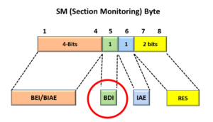
The Network Element will send the OTUk-BDI indicator by setting the BDI bit-field (Bit 5) within the SM (Section Monitoring) Byte, to  1, within each outbound OTUk frame.

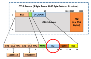
The SM byte resides within the 3-byte SM (Section Monitoring) field of the OTUk Overhead.

Figures 4a, 4b, and 4c present the location of the BDI field.
Figure 4a presents an illustration of the SM-field within the OTUk Overhead.

OTUk Overhead with SM Field Identified

Figure 4a, The SM Field within the OTUk Overhead

Further, Figure 4b illustrates the SM byte’s location within the 3-byte SM Field (within the OTUk Overhead).

SM field with the SM Byte identified

Figure 4b, The SM-Byte within the SM Field

Finally, Figure 4c shows the location of the BDI-field within the SM-byte (within the SM-field of the OTUk Overhead).

SM Byte with OTUk-BDI field identified

Figure 4c, The Location of the BDI bit-field within the SM Byte, within the SM Field, within the OTUk Overhead

Likewise, the Network Element will end its transmission of the OTUk-BDI indicator by setting the BDI bit-field back to “0” within each outbound OTUk frame.

How does the OTUk Network Element detect and declare the dBDI indicator?

In the scenario that we described above (via Figure 3), NETWORK ELEMENT EAST will continue to transmit the OTUk-BDI signal to NETWORK ELEMENT WEST as long as it (NETWORK ELEMENT EAST) declares the service-affecting defect within its Ingress (Receive) signal.

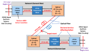
If NETWORK ELEMENT WEST receives the OTUk-BDI indicator within at least five (5) consecutive OTUk frames, it will declare the dBDI defect condition.

In other words, if NETWORK ELEMENT WEST (or any Network Element) were to receive at least five (5) consecutive OTUk frames, in which the BDI bit-field is set to “1”, then it will declare the dBDI defect.

Figure 5 illustrates NETWORK ELEMENT WEST declaring the dBDI defect after receiving five consecutive OTUk Frames with the SM-BDI field set to “1”.

Network Element West declares the dBDI defect condition

Figure 5, Illustration of NETWORK ELEMENT WEST declaring the dBDI defect condition

How does the OTUk Network Element clear the dBDI defect condition?

Whenever NETWORK ELEMENT EAST has determined that the service-affecting defect (which caused it to transmit the dBDI signal in the first place) is cleared, it will stop sending the dBDI signal back out to NETWORK ELEMENT WEST.

NETWORK ELEMENT EAST will stop sending the dBDI signal by setting the BDI bit-field (within the SM field) to “0” within each outbound OTUk frame.

If NETWORK ELEMENT WEST (which is currently declaring the dBDI defect condition) were to receive at least five (5) consecutive OTUk frames, in which the BDI bit-field is set to “0”, then it will clear the dBDI defect.

Figure 6 illustrates NETWORK ELEMENT WEST clearing the dBDI defect after receiving five consecutive OTUk Frames with the SM-BDI field set to “0”.

Network Element East declares Service-Affecting Defect

Figure 6, Illustration of NETWORK ELEMENT WEST clearing the dBDI defect condition

Monkey Pox and Covid? It’s Scary Out There. We Can Help You Become an Expert on OTN Before It’s Safe to Venture Out!! Click on the Banner Below to Learn More!!

Discounts Available for a Short Time!!

For More Information on OTN Posts in this Blog, click on the Image below.

OTN Related Blog

OTN Related Topics within this Blog

OTN Related Topics within this Blog General Topics Consequent Equations - What are they and How can you use them? ...