What is the NULL Test Signal for OTN?

This post defines and describes the NULL Signal for OTN (Optical Transport Network) applications.

What is the NULL Test Signal for OTN?

What Exactly is the NULL Test Signal for OTN?

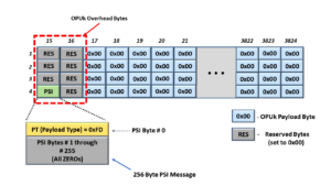
The NULL signal (for OTN) is an OPUk frame with all the following characteristics.

  • The PT (Payload Type) byte-field (within the PSI) is set to the value 0xFD (which indicates that this OPUk frame is transporting the NULL signal).
  • The rest of the 7 RES (Reserved) byte-fields (within the OPUk Overhead) are all set to an All-Zeros pattern (0x00).
  • All the payload bytes (within the OPUk frame) are set in an All-Zeros pattern.

Figure 1 shows a drawing of an OPUk Frame transporting the NULL signal.
OPUk_Frame transporting NULL Signal

Figure 1, An Illustration of the OPUk frame that is transporting the NULL signal

Any ODUk or OTUk frame that transports an OPUk frame with these characteristics carries the NULL signal.

Additionally, any of the following types of OPUk/ODUk signals can transport the NULL signal:

  • OPU0/ODU0
  • OPU1/ODU1
  • OPU2/ODU2
  • OPU2e/ODU2e
  • OPU3/ODU3
  • OPU4/ODU4
  • OPUflex/ODUflex

Clueless about OTN? We Can Help!! Click on the Banner Below to Learn More!!

Corporate Discounts Available!!!

Where and How would one use the NULL Signal?

ITU-T G.709 defines the NULL signal (for OTN) as a test signal.

Therefore, the System Architect can consider the NULL signal as a tool (in the toolbox) for testing and debugging features available to an OTN system.

Some system applications will transmit the NULL signal via the Protection Transport entity within a 1:1 or 1:n protection switching scheme.  In this case, the user will send the NULL signal instead of either the Extra-Traffic Signal or the ODUk-OCI Maintenance Signal.

Figure 2 shows a drawing of the 1:2 Protection Switching scheme, in which the user is transporting the NULL signal via the Protection Transport Entity.

1:2 Protection Switching scheme using the NULL Signal

Figure 2, An Illustration of a 1:2 Protection Switching scheme that is transporting the NULL signal via the Protection Transport entity

We can use the NULL signal in any application or situation whenever we need to continuously supply an optical signal (that is carrying timing information) to keep Clock Recovery PLL circuitry (within a downstream Network Element) locked onto the timing signal in the local Network Element.

Simultaneously, the NULL signal will indicate to the downstream Network Element that the connection is working correctly and that there are no defects upstream.

The NULL signal is unlike an AIS signal, which does indicate (to downstream Network Elements) the presence of service-affecting defect conditions upstream.

How Should a System Designer create the NULL Signal for OTN Applications?

The NULL signal (for OTN applications) consists of a fixed pattern.

Therefore, the user can generate OPUk signals (transporting the NULL signal) using a Pattern Generator, which gets its timing from a local clock oscillator.

The System Designer must also ensure that this NULL Signal generator function generates both the OTUk/ODUk Frame and Multi-Frame start indicators.

The Frame Start indicator (FS) should occur every 122,368 clock cycles (or ODUk frame period).

And the Multi-Frame Start indicator (MFS) should occur every 256 frames.

ITU-T G.798 specifies an adaptation function of the name ODUkP/NULL_A_So.

This function is responsible for generating an ODUk signal transporting the NULL signal.

This adaptation function generates the NULL signal from a free-running clock source, which then maps this signal into an OPUk/ODUk frame.

Finally, this function includes the OPUk overhead (e.g., the RES and PT fields) and a default ODUk overhead.

NOTE:  In the case of the default ODUk overhead, this function will set all the ODUk overhead fields to All-Zeros, except for the PM STAT field, which will be set to the value 001 (to indicate a Normal Path Signal).

Figure 3 illustrates the ODUkP/NULL_A_So function from ITU-T G.798.

ODUkP/NULL_A_So function block diagram

Figure 3 illustrates the ODUk/NULL_A_So function from ITU-T G.798.  

What are the Timing (Frequency Accuracy), Jitter, and Wander Requirements for the NULL Signal?

Please see the ODCa (ODU Clock for Asynchronous Mapping) post for the complete Frequency Accuracy and Jitter/Wander requirements of this NULL signal.

Summary

The NULL signal, for OTN applications, is an OPUk frame that has ALL the following characteristics:

  • All the Payload bytes have the value 0x00 (All Zeros).
  • The PT (Payload Type) byte (within the PSI message) has the value of 0xFD (which identifies this particular signal as being the NULL signal)
  • All remaining OPUk overhead fields will be of the value of 0x00 (All Zeros).

Additionally, within the ODUk overhead, the PM STAT field should be set to the value 001.

The NULL signal is a test signal that one can use for test and debugging purposes.

The System Design can also use the NULL signal as a replacement signal for a signal that is unavailable due to user configuration reasons.

Has Inflation got You Down? Our Price Discounts Can Help You Beat Inflation and Help You Become an Expert on OTN!! Click on the Banner Below to Learn More!!

Discounts Available for a Short Time!!

For More Information on OTN Posts in this Blog, click on the Image below.

OTN Related Blog

OTN Related Topics within this Blog

OTN Related Topics within this Blog General Topics Consequent Equations - What are they and How can you use them? ...

What is 1+1 Protection Switching (APS)

This post defines and describes the term 1+1 Protection Switching.


What is 1+1 Protection Switching?

ITU-T G.808 Defines 1+1 (Protection) Architecture as:
A 1+1 protection architecture has one normal traffic signal, one working transport entity, one protection transport entity, and a permanent bridge.
At the source end, the normal traffic signal is permanently bridged to both the working and the protection transport entities.  

At the sink end, the normal traffic signal is selected from the better of the two transport entities.

Due to the permanent bridging, the 1+1 (protection) architecture does not allow an unprotected extra traffic signal to be provided.  

What Does All This Mean?

As for all Protection Groups, a 1+1 Protection Architecture consists of the following elements.

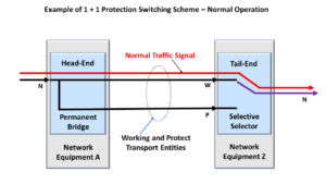
Figure 1 presents an illustration of a 1+1 Protection Switching Architecture.

1+1 Protection Switching Architecture - Normal Operation

Figure 1, Illustration of a 1+1 Protection Switching Architecture – Normal (No Defect) Condition

How to Know if You’re Working with a 1+1 Protection Architecture?

This figure shows that a Permanent Bridge realizes the Head-End (of this Protection Group) and that a Selector Switch realizes the Tail-end.  This is a crucial characteristic of the 1+1 Protection Architecture.  

As we defined earlier (from the excerpts of ITU-T G.808), the Permanent Bridge means that there is a hardwired connection between the Normal Traffic Signal and both the Working and Protection Transport entities at the Head-End circuitry.  This fact helps you to identify a 1+1 Protection Architecture quickly.  This is not the case for a 1:N Protection Architecture.  

You can see all of this in Figure 1.  

No-Defect Operation of the Normal Traffic Signal in a 1+1 Protection Architecture

The Normal Traffic Signal will travel through the Working Transport entity for normal conditions, as shown in Figure 1.

Although the Normal Traffic signal is bridged (or connected) to both the Working and Protect Transport entities, it only flows through the Working Transport entity because we connected the Selector switch to the Working Transport entity.

Whereas the Selector Switch leaves the connection between the Protection Transport entity and the Tail-End circuitry, OPEN.

Clueless about OTN and Protection Switching? We Can Help!!! Click on the Banner Below to Learn More!!!

Corporate Discounts Available!!!

A Service-Affecting Defect occurs.

Now, let us look and see what happens if “bad things” occur.

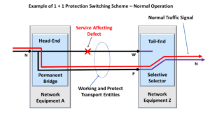
Figure 2 presents an illustration in which an impairment now exists within the Working Transport entity; this impairment causes the Protection Controller (not shown but sitting behind the Tail-end circuitry) to declare a Service-Affecting defect (e.g., SF) or SD.

1+1 Protection Switching Architecture - Defect Condition

Figure 2, Illustration of a Service-Affecting Defect within the Working Transport entity

In this case, the Normal Traffic signal can no longer travel through the Working Transport entity.

If our circuitry did not have any protection switching capability, then all the customers (and end-users) of the Normal Traffic Signal would lose their service.

This would be very bad, especially for the service provider and their financial future.

Protection Switching Occurs

Fortunately, this system does offer protection switching.

In this case, since the Protection Controller has detected and declared a service-affecting defect condition within the Working Transport entity signal, it will then switch the Selector such that it is now connected to the Protect Transport entity, as we show in Figure 3.

1+1 Protection Switching - Protection Switching Condition

Figure 3, Illustration of Normal Traffic signal flow – following Protection Switching

Once the Selector switches over and connects to the Protection Transport entity, the Normal Traffic signal will flow through the Protection Transport entity.

This is an excellent thing for all parties involved.

The users (of the Normal Traffic signal) will get their data or have their service still available.  And the service provider will have fewer irate customers and nasty phone calls.

Other Considerations for 1+1 Protection Switching

The 1+1 Protection Switching Architecture is quite simple.

We usually implement the head-end with a Permanent Bridge and realize the tail-end with a Selector switch.

However, there are some variations that we need to consider for the 1+1 Protection Switching architecture.

Unidirectional or Bidirectional Switching

The user can design their 1+1 Protection Switching architecture to be either a Unidirectional or Bidirectional type.

Please see the Unidirectional and Bidirectional Protection Switching posts for more details on these terms.

NOTE:  If you intend to use Bidirectional Protection Switching, then you will need to use some form of APS communication link/protocol to coordinate the switching of both ends of the protection group.

Protection Ratio:

The protection ratio for a 1+1 Protection Switching system is not very good.  This situation is not good because the user must design twice (2X) the bandwidth of the Normal Traffic signal.

We have to allocate 1X of the bandwidth for the Working Transport entity and 1X for the Protection Transport entity.

To Revert or Not-Revert

If a Protection Switching architecture supports “revert” (or reverting), then this means that the Selector switch will automatically switch back to the Working Transport entity once the service-affecting defect (which caused the switching event) has cleared.

Please see the post on revert for more details about this option.

Has Inflation got You Down? Our Price Discounts Can Help You Beat Inflation and Help You Become an Expert on OTN and Protection-Switching!! Click on the Banner Below to Learn More!!

Discounts Available for a Short Time!!

Click on the Image Below to see more Protection-Switching related content on this Blog:

Protection-Switching Related Blog

Protection-Switching Related Blog Posts

Protection-Switching Related Blog Posts Basic Protection-Switching Terms Head-End (Source Node) Hold-Off Timer Protection-Group Protection-Transport entity Selector Switch Tail-End (Sink Node) ...

What is the Tail-End for Protection Switching?

This post defines and describes the term Tail-End for (APS) Automatic Protection Switching applications.


What is the Tail-End within an APS (Automatic Protection Switching) System?

ITU-T G.808 Defines the Tail-End as:

The tail-end of a protection group is the end where the selector process is located.  In the case where traffic is protected in both directions of transmission, the tail-end process is present at every end of the protection group.

NOTE:  Whenever people discuss the tail-end of an APS system, they will sometimes use the term sink node.

ITU-T G.808 Defines the Sink Node (within a Protection Group) as:

The node at the egress of a protected domain, where a normal traffic signal may be selected from either the working transport entity or the protection transport entity.

So What Does All This Mean?

In Figure 1, we present an illustration of a Protection Group.

If we were to look closely at the Normal Traffic Signal (in Figure 1), we would see that the Tail-End is the last component that the Normal Traffic signal passes through as it exits the Protection Group.

Protection Group - 1:N

Figure 1, Illustration of a Protection Group

The Tail-End (or Sink Node) circuitry is responsible for declaring and clearing defects and asserting (or de-asserting) the SF (Signal Fail) and SD (Signal Degrade) indicators.

The Sink Node (or Tail-End) will use these SF and SD indicators to select either the Working or Protect Transport entity as its source for the Normal Traffic Signal.

Figure 2 illustrates a simplified schematic within the Tail-End Circuitry (including the Protection-Switching Controller).  

Tail End Circuitry - Protection-Switching Controller for a 1+1 Protection Architecture

Figure 2, Illustration of the Tail-End Circuitry

Additionally, Figure 2 shows that the Tail-End Circuitry contains circuitry that detects and declares defect conditions and asserts the SF or SD indicators.   This circuitry also includes the Protection-Switching Controller.  I will describe how this circuitry works in another post.  

Another post discusses the SF (Signal Fail) and SD (Signal Degrade) indicators.

As I show in Figure 2, the Tail-End will often use a Selector Switch that connects to the Working or Protection Transport entity.

If the Selector Switch is connected to the Working Transport entity, then the Tail-End circuitry will be using it (the Working Transport entity) as its source of the Normal Traffic signal.

The Normal Traffic signal will then propagate through the Tail-End circuitry as it exits the Protection Group.

But, if the Selector (Switch) is connected to the Protect Transport entity, then the Tail-End circuitry will be using the Protect Transport entity as its source of the Normal Traffic signal.

USING THE SELECTOR IN A 1+1 AND 1:N PROTECTION SWITCHING ARCHITECTURE

Figures 3 and 4 show drawings of the Protection Group using a Selector (Switch) in a 1+1 and 1:2 Protection Switching scheme, respectively

Selector in a 1+1 Protection Switching System

Figure 3, Illustration of a Selector within a 1+1 Protection Switching Scheme

Selector in a 1:2 Protection Switching System

Figure 4, Illustration of a Selector within a 1:2 (1:N) Protection Switching Scheme

In the case of the 1+1 Protection Switching scheme, the Working and Protect Transport entities always carry the Normal Traffic Signal.

However, the Protection Switching controller function within the Tail-End circuitry (not shown in Figure 3) will determine whether to select the Normal Traffic signal from the Working or the Protect Transport entity.

Suppose the Protection Switching controller function was to declare (for example) the SF (Signal Fail) or SD (Signal Degrade) defect condition within the Normal Traffic signal passing through the Working Transport entity.  In that case, it will command the Selector Switch to switch over and connect to the Protect Transport entity.

Whenever the Selector Switch switches from the Working to the Protect Transport entities, we call this action protection switching.

Some Protection Groups support a revert feature, where the Selector Switch automatically switches back to connecting to the Working Transport entity after the SF or SD defect has cleared.

Other Protection Groups are non-reverting systems and do not support this feature.

In other blog posts, we discuss the Protection Switching controller function and the revert operation.

Clueless about OTN and Protection Switching? We Can Help!!! Click on the Banner Below to Learn More!!!

Corporate Discounts Available!!!

THE NEED FOR COMMUNICATION BETWEEN THE TAIL-END AND HEAD-END COMPONENTS OF A PROTECTION GROUP

The Selector Switch will connect to either the Working or Protect Transport entity, depending upon whether the Protection Switching controller circuitry declares the SF or SD defect within the Normal Traffic signal traveling through these transport entities.

The circuitry that detects and declares these defects (and commands the Selector to switch) resides on the Tail-End side of the Working/Protect Transport entities.

Therefore, in many Protection Switching architectures (e.g., 1:1, 1:n, and Bidirectional 1+1), the Tail-End will need to communicate and coordinate its protection-switching actions with the Head-End circuitry (within the Protection Group) via a communication link.

We discuss this APS communication link (or protocol) in another blog post.

Summary

The Tail-End (called the Sink Node) is usually the last component that a Normal Traffic Signal will pass through as it leaves the Protection Group.

The Tail-End (or Sink Node) contains circuitry that will determine if it should declare any service-affecting defects with the Working and Protect Transport entities and assert the SF (Signal Fail) signal as appropriate.

This Tail-End circuitry will also check the Working and Protect Transport entities for excessive errors (within the OTUk/ODUk signal) and assert the appropriate SD (Signal Degrade) signal.

The Sink Node (or Tail-End) circuitry will use these SF and SD signals to decide whether the Selector Switch should select the Normal Traffic Signal from the Working or the Protect Transport entities.

For normal (no defect) conditions, the Selector Switch will connect to and accept the Normal Traffic Signal from the Working Transport entity.

In this case, the Normal Traffic signal will travel from the Working Transport entity to and through the Tail-end circuitry as it leaves the Protection Group.

However, suppose the Protection-Switching controller determines that the Normal Traffic signal, when passing through the Working Transport entity, contains service-affecting defects, such as SF or SD.  In that case, it will command the Selector Switch to switch over and connect to the Protect Transport entity.

In this case, the Selector will now obtain the Normal Traffic signal from the Protect Transport entity (instead of the Working Transport entity).

Whenever the Selector switches from the Working to the Protect Transport entity, we call this action Protection Switching.

Has Inflation got You Down? Our Price Discounts Can Help You Beat Inflation and Become an Expert on OTN and Protection-Switching!! Click on the Banner Below to Learn More!!

Discounts Available for a Short Time!!!

Click on the Image Below to see more Protection-Switching related content on this Blog:

Protection-Switching Related Blog

Protection-Switching Related Blog Posts

Protection-Switching Related Blog Posts Basic Protection-Switching Terms Head-End (Source Node) Hold-Off Timer Protection-Group Protection-Transport entity Selector Switch Tail-End (Sink Node) ...

What is the Head-End for Protection Switching?

This post defines and describes the term head-end for APS (Automatic Protection Switching) applications.


What is the Head-End, within an APS (Automatic Protection Switching) System?

ITU-T G.808 Defines the Head-end as:

The head-end of a protection group is the end where the bridge process is located.  If traffic is protected in both directions of transmission, the head-end process is present at every end of the protection group.  

NOTE:  Whenever people discuss the head-end of an APS system, they sometimes use the alternative term source-node.

ITU-T G.808 Defines the Source-Node as:

The node at the Ingress to a protected domain, where a normal traffic signal may be bridged to the protection transport entity.  

So What Does All This Mean?

In Figure 1, we show a drawing of a Protection Group.

If we were to look closely at the Normal Traffic Signal (within Figure 1), we would see that the Head-end is the first component that the Normal Traffic Signal passes through as it enters the Protection Group.

Protection Group - 1:N

Figure 1, Illustration of a Protection Group

The Head-end (or Source Node) is responsible for connecting the Normal and Extra Traffic Signals to the Working and Protect Transport entities, as appropriate for APS applications.

The Head-end will typically use a Bridge to connect the Normal Traffic signals and the Extra Traffic Signal (if available) to the Working and/or Protect Transport entities.

Automatic Protection Switching typically uses one of two types of Bridges.

  • The Permanent Bridge and
  • The Broadcast Bridge

We will discuss each of these bridges below.

The Permanent Bridge – (for the 1+1 Protection Switching Architecture)

If you use the 1+1 Protection Switching Architecture, you will typically use the Permanent Bridge.

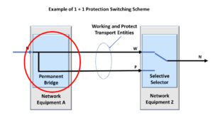
The Permanent Bridge (as its name implies) permanently bridges (e.g., connects) the Normal Traffic Signal to both the Working and Protect Transport Entities.

Figure 2 presents an illustration of a Permanent Bridge.

Permanent Bridge

Figure 2, Illustration of a Permanent Bridge

This means that, for the 1+1 Protection Switching Architecture, the Working and Protect Transport entities always carry the Normal Traffic Signal.

In this case, the Bridge also acts as a “splitter” that transmits the Normal Traffic signal via the Working Transport entity and a replica of the Normal Traffic signal via the Protect Transport entity.

Figure 3 shows a drawing of a Protection Group that uses the 1+1 Protection Switching Architecture.

Protection Group - 1+1

Figure 3, Illustration of a Protection Group that uses the 1+1 Protection Switching Architecture

The Broadcast Bridge – (for the 1:1 and 1:n Protection Switching Architecture)

If you are using the 1:1 or 1:n Protection Switching Architecture, you will typically use the Broadcast Bridge.

For the one or n Working Transport entities (for the 1:1 or 1:n protection switching architectures, respectively), the Broadcast Bridge will permanently connect the Normal Traffic Signal to the Working Transport entity.

The Broadcast Bridge will (upon protection-switching controller command or configuration) also connect its corresponding Normal Traffic signal to the Protect Transport Entity.

We discuss the protection-switching controller in another blog post.

The 1:1 or 1:n Protection Switching Architecture may also include an Extra Traffic signal, which travels through the Protect Transport entity whenever none of the Working Transport entities declare service-affecting or signal degrade defect conditions.

Below, Figure 4 presents an illustration of the Broadcast Bridge.

Broadcast Bridge

Figure 4, Illustration of a Broadcast Bridge (for 1:1 and 1:n Protection Switching schemes)

Additionally, Figure 5 presents an illustration of a Protection Group that uses the 1:2 Protection Switching Architecture and (thus) uses Broadcast Bridges within its Head-End circuitry.

1:2 Protection Switching System

Figure 5, Illustration of a Protection Group that uses the 1:2 Protection Switching Architecture

Summary

The Head-End (called the “Source Node”) is usually the first component that a Normal Traffic Signal will pass through as it enters a Protection Group.

The Head-End (or Source Node) performs a Bridging Function between the Normal Traffic Signal and the Working and Protect Transport Entities.

We use two basic types of bridging functions in Protection Switching applications.

The Permanent Bridge permanently connects the Normal Traffic signal to the Working and Protect Transport entities.

A Broadcast Bridge permanently connects the Normal Traffic signal to the Working Transport entities.

Finally, the Broadcast Bridge will (upon user command or configuration) also connect the corresponding Normal Traffic signal to the Protect Transport entity.

Has Inflation got You Down? Our Price Discounts Can Help You Beat Inflation and Become an Expert on OTN!! Click on the Banner Below to Learn More!!

Discounts Available for a Short Time!!!

Click on the Image Below to see more Protection-Switching related content on this Blog:

Protection-Switching Related Blog

Protection-Switching Related Blog Posts

Protection-Switching Related Blog Posts Basic Protection-Switching Terms Head-End (Source Node) Hold-Off Timer Protection-Group Protection-Transport entity Selector Switch Tail-End (Sink Node) ...

What is a Protection Group (APS)

This post defines the term Protection Group, for Automatic Protection Switching (APS) purposes.


What is a Protection Group for APS (Automatic Protection Switching) Purposes?

ITU-T G.808 Defines the Protection Group as:  

The collection of head-end and tail-end functions, 1 to n normal traffic signals, optionally an extra traffic signal, 1 to n working transport entities, and a single protection transport entity used to provide extra reliability for the transport of normal traffic signals.

What does all that mean?

The Protection Group comprises components and connections that work together to enhance the reliability of a transmission/network system for a Normal Traffic Signal by implementing Automatic Protection Switching.

Further, the Protection Group for a transmission/networking system consists of all the following items/entities.

The Protection Group enhances the reliability and protects 1 to N numbers of Normal Traffic Signals.

The Protection Group can either support Unidirectional or Bidirectional protection switching.

Figure 1 presents the Illustration of a 1+1 Protection scheme that I have modified to show the various elements within a Protection Group.

Protection Group - 1+1

Figure 1, Illustration of a 1+1 Protection Scheme that also identifies the Protection Group.

Likewise, Figure 2 illustrates a 1:2 Protection scheme that I have modified to show the various elements within the Protection Group.

Protection Group - 1:N

Figure 2, Illustration of a 1:2 Protection Scheme that also identifies the Protection Group.

In both cases, Figures 1 and 2 show numerous components within a shaded box.

All the items within the shaded box (in each figure) make up the Protection Group.

I discuss the individual components that make up the Protection Group in other posts within this post.

In Summary:

A Protection Group is a system that consists of the following items/entities:

Each of these components works together, using Automatic Protection Switching to enhance the transport path’s reliability for a given Normal Traffic Signal.

Has Inflation got You Down? Our Price Discounts Can Help You Beat Inflation and Help You Become an Expert on OTN!! Click on the Banner Below to Learn More!!

Discounts Available for a Short Time!!

Click on the Image Below to see more Protection-Switching related content on this Blog:

Protection-Switching Related Blog

Protection-Switching Related Blog Posts

Protection-Switching Related Blog Posts Basic Protection-Switching Terms Head-End (Source Node) Hold-Off Timer Protection-Group Protection-Transport entity Selector Switch Tail-End (Sink Node) ...

Bidirectional Protection Switching

This post defines the term Bidirectional Protection Switching for APS (Automatic Protection Switching) applications.


What is Bidirectional Protection Switching (and How is it Different from Unidirectional Protection Switching)?

The Definition of Bidirectional Protection Switching

ITU-T G.780 defines Bidirectional Protection Switching as follows:

A protection switching architecture in which, for a unidirectional failure (i.e., a failure affecting only one direction of transmission), both directions (of the “trail,” “subnetwork connection,” etc.), including the affected direction and the unaffected direction, are switched to protection.  

What does All That Mean?

I will explain all this through three (3) illustrations/cases.

  • The Normal/No Defect Case
  • The Defect/Bidirectional Protection Switching Case and
  • The Defect/Unidirectional Protection Switching Case

The Normal/No Defect Case

Figure 1 illustrates a “Normal” (e.g., No Defect) condition.

This illustration shows two network elements transmitting and receiving traffic to and from each other.

We will call one of these network elements Network Element West and the other network element Network Element East.

Normal Traffic/No Defect Condition - Protection Switching

Figure 1, Illustration of two Network Elements exchanging traffic during Normal/No-defect conditions.

Figure 1 also shows Protection Switching support for the traffic flow between these two Network Elements.

This figure shows a Bidirectional Working Transport Entity between these two Network Elements.

The figure also shows that there is a Bidirectional Protection Transport Entity between these two Network Elements, as well.

In this case, neither Network Element declares any defect within the Working Transport Entity, and Good/Normal Bi-directional traffic flows between these two Network Elements.

Finally, this figure also shows that all the traffic flows through the Working Transport Entities and that none of the traffic flows through the Protect Transport Entities.

Next, we will consider what happens whenever one Network Elements declares a service-affecting defect within the Working Transport Entity.

Bidirectional Protection Switching Case

Figure 2 presents an illustration of a Defect condition.

In this case, some impairment exists within the West-to-East Working Transport connection, and Network Element East is declaring some service-affecting defect with this traffic signal.

Bidirectional Protection Switching

Figure 2, Illustration of Bidirectional Protection Switching – in response to a Service-Affecting Defect in one direction of traffic

Since this defect exists within the Working Transport connection (in the West-to-East direction), this protection switching scheme will route all West-to-East traffic through the Protect Transport Entity instead.

Yet, this protection scheme does not stop there.  It will also route all East-to-West traffic through the Protect Transport entity.

In other words, if we detect a defect within the Working Transport Entity (at all), we will route traffic for BOTH directions from the Working Transport entity to the Protect Transport entity.

We call this particular protection scheme Bidirectional Protection Switching because, in this case, we are performing protection switching in BOTH directions, even if we only declare a service-affecting defect in one direction.

NOTE:  Since we perform protection switching in BOTH directions (for bidirectional protection switching), this kind of protection scheme requires that the protection group uses an APS or PCC (Protection Communications Channel).

Both ends of the protection group will need to communicate and coordinate with each other during protection switching events.

We will clarify the difference between Bidirectional and Unidirectional Protection Switching by showing the Unidirectional Protection Switching Case.

Unidirectional Protection Switching Case

Figure 3 presents another illustration of a Defect condition.

In this case, there is (once again) some impairment that exists within the West-to-East Working transport connection, and Network Element East is declaring some service-affecting defect with this traffic signal.

Unidirectional Protection Switching

Figure 3, Illustration of Unidirectional Protection Switching – responds to a Service-Affecting Defect in one direction on traffic.

Since this defect exists within the Working Transport Entity, this protection scheme will route all West-to-East traffic through the Protect Transport entity.

Yet, in contrast to the Bidirectional Protection Switching scheme, it will continue to route all East-to-West traffic through the Working Transport entity; since there are no defects in that particular direction.

In other words, the Unidirectional Protection Switching scheme only routes the traffic directions (the Network Element has determined to be defective) through the Protect Transport Entity.

If it detects no defects within a given Working Transport entity (in the other direction), it will continue to route that traffic through the Working Transport entity.

We call this particular protection scheme Unidirectional Protection Switching because, in this case, we are performing protection switching in ONE direction if we only detect a service-affecting defect in ONE direction.

Please see the Unidirectional Protection Switching post for more detailed information on this protection switching scheme.

Summary

In summary, the main difference between Unidirectional and Bidirectional Protection switching is as follows.

For Bidirectional Protection Switching, if the Network Elements declare a service-affecting defect in ONLY one direction (of traffic), the protection scheme will still switch BOTH directions of traffic from the Working to the Protect Transport entity.

In the case of Unidirectional Protection Switching, if the Network Elements declare a service-affect defect in ONLY one direction (of traffic), then the protection scheme will only switch the defective direction from the Working Transport entity to the Protect Transport entity.

The other (non-defective) direction of traffic will continue to use the Working Transport Entity.

Has Inflation got You Down? With Our Pricing Special, You Can Beat Inflation and Become an Expert on OTN!! Click on the Banner Below to Learn More!!

Discounts Available for a Short Time!!!

Click on the Image Below to see more Protection-Switching related content on this Blog:

Protection-Switching Related Blog

Protection-Switching Related Blog Posts

Protection-Switching Related Blog Posts Basic Protection-Switching Terms Head-End (Source Node) Hold-Off Timer Protection-Group Protection-Transport entity Selector Switch Tail-End (Sink Node) ...

Unidirectional Protection Switching

This post defines the term Unidirectional Protection Switching for APS (Automatic Protection Switching) applications.


What is Unidirectional Protection Switching (and How is it Different from Bidirectional Protection Switching)?

The Definition of Unidirectional Protection Switching

ITU-T G.780 defines Unidirectional Protection Switching as follows:

A protection switching architecture in which, for a unidirectional failure (i.e., a failure affecting only one direction of transmission), only the affected direction (of the “trail,” or “subnetwork connection,” etc.) is switched to protection.  

What does ALL that Mean?

I will explain all this through three illustrations/cases

  • The Normal/No Defect Case
  • The Defect/Unidirectional Protection Switching Case and
  • The Defect/Bidirectional Protection Switching Case

The Normal/No Defect Case

Figure 1 illustrates a “Normal” (e.g., No Defect) condition.

This illustration shows two network elements transmitting and receiving traffic to and from each other.

We will call one of these Network Elements Network Element West and the other Network Element Network Element East.

Normal Traffic/No Defect Condition - Protection Switching

Figure 1, Illustration of two Network Elements exchanging traffic during Normal/No-defect conditions.  

Figure 1 also shows Protection Switching support for the traffic flow between these two Network Elements.

This figure shows a Bidirectional Working Transport Entity between these two Network Elements.

The figure also shows that there is a Bidirectional Protect Transport Entity between these two Network Elements, as well.

In this case, neither Network Element declares any defect within the Working Transport Entity, and Good/Normal Bi-directional traffic flows between these two Network Elements.

Finally, this figure also shows that all the traffic flows through the Working Transport Entities and that none of the traffic flows through the Protect Transport Entities.

Next, we will consider what happens whenever one Network Elements declares a service-affecting defect within the Working Transport Entity.

Unidirectional Protection Switching Case

Figure 2 presents an illustration of a “Defect” condition.

In this case, some impairment exists within the West to East Working Transport entity, and Network Element East is declaring some service-affecting defect with this traffic signal.

Unidirectional Protection Switching


Figure 2, Illustration of Unidirectional Protection Switching – in response to a Service-Affecting Defect in one direction of traffic

Since this defect exists within the Working Transport entity (in the West-to-East direction), this protection switching scheme will route all West-to-East traffic through the Protect Transport Entity instead.

Please note this protection switching event only applies to the traffic within the West-to-East Direction.

Since Network Element West is not declaring any defects within the East-to-West Working Transport Entity, the East-to-West traffic will continue to travel via the Working Transport Entity (even though the West-to-East traffic has been switched over to the Protect Transport Entity.

We call this particular protection scheme Unidirectional Protection Switching because, in this case, we only perform protection switching in the ONE direction that has the service-affecting defect.

We will clarify the difference between Unidirectional and Bidirectional Protection Switching by showing the Bidirectional Switching Case.

Bidirectional Protection Switching Case

Figure 3 presents another illustration of a Defect condition.

In this case, there is (once again) some impairment that exists within the West-to-East Working transport connection, and Network Element East is declaring some service-affecting defect with this traffic signal.

Bidirectional Protection Switching

Figure 3, Illustration of Bidirectional Protection Switching – in response to a Service-Affecting Defect in one direction of traffic

Since this defect exists within the Working Transport connection, this protection switching scheme will route all “West-to-East” traffic through the Protect Transport entity instead.

Yet, this protection switching scheme does not stop there.  It will also route all East-to-West traffic through the Protect Transport entity.

In other words, if we detect a defect within the Working Transport Entity (at all), we will route the traffic for BOTH Directions from the Working Transport entity to the Protect Transport entity.

We call this particular protection scheme Bidirectional Protection Switching because, in this case, we are performing protection switching in BOTH directions, even if we only detect a service-affecting defect in one direction.

Please see the Bidirectional Protection Switching post for more detailed information on this protection switching scheme.

Summary

In summary, the main difference between Unidirectional and Bidirectional protection switching is as follows.

For Unidirectional Protection Switching, if the Network Elements declare a service-affecting defect in ONLY one direction (of traffic), then the protection scheme will only switch the defected traffic direction from the Working Transport Entity to the Protect Transport Entity.  The other (non-defective) traffic direction will continue to use the Working Transport Entity.

In the case of Bidirectional Protection Switching, if the Network Elements declare a service-affecting defect in ONLY one direction (of traffic), then the protection scheme will switch BOTH directions of traffic from the Working Transport Entity to the Protect Transport Entity.

Has Inflation Got You Down? With Our Special Pricing, You Can Beat Inflation, and You Can Be an Expert on OTN!! Click on the Banner Below to Learn More!!

Discounts Available for a Short Time!!!

Click on the Image Below to see more Protection-Switching related content on this Blog:

Protection-Switching Related Blog

Protection-Switching Related Blog Posts

Protection-Switching Related Blog Posts Basic Protection-Switching Terms Head-End (Source Node) Hold-Off Timer Protection-Group Protection-Transport entity Selector Switch Tail-End (Sink Node) ...

What is the RDI (Remote Defect Indicator)?

This post presents a generic definition of the term: RDI (Remote Defect Indicator) signal. It also describes how and when Network Equipment will transmit this type of signal.


What is the RDI (Remote Defect Indicator) Signal?

What does RDI Mean?

RDI is an acronym for Remote Defect Indicator.

Where is the RDI Signal Used?

RDI is a particular type of alarm signal that a Network Element (within a Telecom/Datacom application) will generate and transmit (back towards upstream Network Equipment) anytime it detects a servicing-affect defect within the signal from that same upstream Network Equipment.

Stated differently, the Network Element (NE) will transmit the RDI indicator (upstream) at the same time (and under the same conditions) that it will send the AIS signal downstream.

For example:  If an NE were to declare the LOS (Loss of Signal) or the LOF (Loss of Frame) defect within its incoming telecom/datacom signal, then it will respond to this defect condition by transmitting the RDI signal (back) upstream towards the source of the defective signal.

Whenever the Network Element transmits this RDI signal upstream, it notifies the upstream NE that there are problems with its data.

What EXACTLY is an RDI Signal?

The method we use to transmit the RDI signal depends upon the telecom/datacom standard and network layer we use.

However, in most cases, the Network Element will transmit the RDI signal by setting a certain overhead bit-field (within the signal it is transmitting back to the remote or upstream NE) to “1”.

The Network Element will continue to set this bit-field to “1” within each data frame (transmitting back to the remote NE) for as long as it declares the defect within its incoming data stream.

Likewise, once the Network Element clears the service-affecting defect, it will stop sending the RDI signal by clearing that same overhead bit-field to “0”.

For OTN applications, we call the RDI signal the BDI (or Backward Defect Indicator) signal.

I have included posts that describe the BDI signal for both the OTUk and ODUk frames.

For example, SONET Line-Terminating Equipment will transmit the RDI-L indicator, and SONET Path-Terminating Equipment will send the RDI-P indicator.

In the case of PDH signals (e.g., T1/E1 or T3/E3), we call the RDI signal by other synonymous names such as FERF (Far-End Receive Failure) or the “Yellow Alarm.

Clueless about OTN? We Can Help!! Click on the Banner Below to Learn More!!!

Discounts Available for a Short Time!!!

When do we transmit the RDI Signal?

We will use a couple of examples to illustrate how and when we transmit the RDI signal.

Example # 1 – The Unerred/Normal Condition

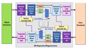
Figure 1 presents a simple illustration of a portion of a 3R Repeater/Regenerator, which consists of the following components:

  • Two (2) Receive Line Interface blocks (one block is labeled W for West, and the other block is labeled E for East)
  • Two (2) Receive Framer blocks (W – West and E – East)
  • Two (2) Transmit Line Interface blocks (W – West and E – East)
  • Two (2) Transmit Framer blocks (W – West and E – East)
  • CS (Clock Smoothing/Jitter Attenuation) PLL (Phase-Locked Loop)
  • AIS OSC (Stand-Alone Oscillator)
  • FIFO/Buffer
  • Two (2) Defect Decoder blocks (W – West and E – East)

In this figure, our 3R Repeater/Regenerator receives a good (error-free) signal from the West Terminal.

The 3R Repeater/Regenerator will first receive this signal through its Receive Line Interface (W) block.

Afterward, this signal passes through to the Receive Framer (W) block.

If the Receive Line Interface (W) and Receive Framer (W) blocks were to declare no problems within this signal.  The 3R Repeater/Regenerator would allow this signal to pass through both the Transmit Framer (E) and Transmit Line Interface (E) blocks as is.

The Receive Line Interface (W) and the Receive Framer (W) blocks would also do nothing to alter the data that the Near-End Transmitter circuitry (e.g., the Transmit Line Interface (W) and Transmit Framer (W) blocks) is transmitting back out to the West Terminal.

Figure 1 presents an illustration of this Normal (No Defect) Condition.

3R Repeater/Regenerator during Normal Conditions

Figure 1, Illustration of the 3R Repeater/Regenerator – during Good/Normal Conditions.

Please note that I have grayed out the non-relevant portions of Figure 1 to focus our discussion on this Defect Declaration to the RDI Generation mechanism on the West-side of the 3R Repeater/Regenerator circuit.

Let’s discuss the case where we will transmit the RDI indicator.

Example # 2 – The dLOS/Abnormal Condition

Figure 2 presents another simple illustration of a 3R Repeater/Regenerator.

However, in this figure, there is an impairment in the signal that originates from the West Terminal such that our Network Element is now declaring the dLOS (Loss of Signal) defect with this signal.

It is possible that a backhoe or some other mishap severed this signal.

Nonetheless, this means that our 3R Repeater/Regenerator is no longer receiving its signal from the West Terminal.

In this case, the 3R Repeater/Regenerator will respond by doing all the following:

  • The Receive Line Interface (W) or the Receive Framer (W) blocks will declare the dLOS (Loss of Signal) defect with the signal that it is receiving from the West Terminal.
  • The Transmit Framer (E) and the Transmit Line Interface (E) (which sit directly behind the Receive Line Interface and Framer blocks – that are declaring the dLOS condition) will now transmit the AIS indicator (to the East Terminal) as we discussed in the AIS post of this blog.
  • Additionally, the Receive Line Interface (W) and/or the Receiver Framer (W) blocks will also command its “near-end” transmitting circuitry [e.g., the Transmit Framer (W) and Transmit Line Interface (W) blocks] to start sending the RDI signal, back out to the West Terminal.

Figure 2 illustrates the dLOS/RDI Transmission Condition for our 3R Regenerator/Repeater.

3R Repeater/Regenerator when transmitting RDI

Figure 2, Illustration of the 3R Repeater/Regenerator – during the dLOS/Abnormal Condition

The Transmit Framer (W) and Transmit Line Interface (W) blocks will send the RDI indicator to the West Terminal for as long as the Receive Line Interface (W) and the Receive Framer (W) blocks declare the dLOS defect within the signal they are receiving from the West Terminal.

The Transmit Framer (W) and Transmit Line Interface (W) blocks will stop sending the RDI indicator once the Receive Line Interface (W) and the Receive Framer (W) blocks clear the dLOS defect and starts to receive good/normal data from the West Terminal.

In addition to the dLOS defect, the Network Element will transmit the RDI Indicator (upstream) in response to any other service-affecting defects, such as:

  • OTN Applications (Sending the SM-BDI or PM-BDI Indicator)
    • dLOF – Loss of Frame defect
    • dLOM – Loss of Multi-Frame defect
    • dLOFLANE – Loss of Frame defect for Logical Lane (for OTL3.4 or OTL4.4 applications)
    • dLOL – Loss of Lane Alignment defect (for OTL3.4 or OTL4.4 applications)
    • dLOFLOM – Loss of Frame and Multi-Frame defect (for Multiplexed Applications)
    • dLOOMFI – Loss of OMFI defect (for Multiplexed Applications using an ODU4 server signal)
    • dPLM – Payload Type Mismatch (for Multiplexed Applications)
    • dTIM – Trail Trace Identifier Mismatch defect

Please check out the appropriate blog posts to learn more about the SM-BDI or PM-BDI indicators for OTN applications.

Why do we bother to transmit the RDI Signal?

The main reason we send the RDI signal (back to upstream equipment) in response to service-affecting defects is to alert that NE that there is a service-affecting defect within its output signal between its location and that of the next downstream NE.

This notification aids in troubleshooting and system debugging of fault conditions in the network.

Inflation’s Got You Down? Our Discounts Can Help You Beat Inflation and Make You an Expert on OTN!! Click on the Banner Below to Learn More!!!

Discounts Available for a Short Time!!!

What is the ODUk-AIS Signal?

This post defines the ODUk-AIS Maintenance Signal. It also discusses when Network Equipment should transmit this Maintenance Signal. Finally, this post describes how a Sink PTE will declare and clear the dAIS defect.


What is the ODUk-AIS Maintenance Signal, and How does a Network Element declare the dAIS Defect Condition?

What is the ODUk-AIS Maintenance signal?

AIS is an acronym for Alarm Indication Signal.

Another post describes the general purpose/role of the AIS maintenance signal.

For OTN applications, the Network Equipment (NE) will transmit the ODUk-AIS maintenance signal by overwriting the contents of an entire ODUk frame (e.g., ODU Overhead and Payload Data) with an All-Ones pattern.

NOTE:  The variable k in the expression ODUk can be of any of the following values, depending upon the data rate:  0, 1, 2, 2e, 3, 4, and flex.

If an OTN STE were to map the ODUk-AIS Maintenance signal into an OTUk frame, then the OTN STE will be generating/transmitting a series of OTUk frames in which the FAS, MFAS, and OTUk Overhead fields are all valid.

The STE will compute and generate the FEC field based on the contents within these OTUk frames.

However, these OTUk frames will contain an ODUk Overhead, the OPUk Overhead, and the Payload fields that have been overwritten with an All-Ones pattern.

Figure 1 presents a drawing of an OTUk frame transporting the ODUk-AIS Maintenance signal.

ODUk-AIS Pattern

Figure 1, Drawing of an OTUk frame carrying the ODUk-AIS Maintenance signal.

Please note that the ODUk-AIS pattern differs from the OTUk-AIS pattern (an Unframed PN-11 pattern).

What are the timing/frequency requirements for the ODUk-AIS Maintenance signal?

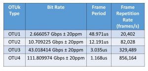
The OTN STE will need to transmit this ODUk-AIS Maintenance signal at the same nominal bit rate as an ordinary ODUk/OTUk signal.

Like any ordinary OTUk signal, the OTN NE will need to transmit this data at the nominal bit-rate ± 20ppm.

Table 1 presents the nominal bit-rates for the OTUk signals (and, in turn, for the OTUk signal, whenever it is transporting the ODUk-AIS indicator) for each value of k.

Table 1, Required Bit Rates for the OTUk signal – when transporting the ODUk-AIS signal.

OTUk Bit Rate

When would OTN Network Equipment transmit/generate the ODUk-AIS Maintenance signal?

An OTN STE will generate/transmit the ODUk-AIS maintenance signal anytime it has detected and declared a service-affecting defect condition (at the OTUk-layer) within the upstream traffic.

For example:  If an STE declares the dLOS-P (Loss of Signal – Path) or the dLOF (Loss of Frame) defect within its incoming OTUk signal, it will respond to this defect condition by transmitting the ODUk-AIS signal downstream.

Whenever the OTN STE transmits this ODUk-AIS maintenance signal downstream, it is (in effect) replacing the missing (or defective) ODUk signal (that the defective OTUk signal was transporting) with the ODUk-AIS maintenance signal.

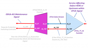
In other words, the OTN STE will generate and transmit the ODUk-AIS Maintenance signal downstream rather than de-map out and transmit an ODUk signal that was likely destroyed by the service-affecting defect within its OTUk server signal.   I show this phenomenon below in Figure 2.

Service Affecting Defect at the OTUk Layer results in the tranmission of the ODUk-AIS Maintenance Signal

Figure 2, Drawing of OTN Circuitry transmitting the ODUk-AIS Maintenance Signal downstream, in response to a Service-Affecting Defect occurring within the OTUk-Layer, upstream.  

The OTN STE will generate and transmit the ODUk-AIS maintenance signal towards downstream ODUk client equipment; anytime it declares any of the following service-affecting defects in the upstream signal.

Please see the post on AIS for an in-depth write-up on when the NE will (and will not) generate the AIS pattern downstream.

How does a Sink PTE detect and declare the ODUk-AIS (or dAIS) defect condition?

The Sink PTE downstream from the STE transmitting the ODUk-AIS Maintenance signal will detect and declare the ODUk-AIS defect condition whenever it receives a STAT field value of “1, 1, 1” within three (3) consecutive OTUk/ODUk frames.

NOTE:  The STAT field is a 3-bit field that resides within the PM (Path Monitor) byte-field in the ODUk overhead.

The Upstream NE will set this 3-bit field to the value [1, 1, 1] because it overwrites the ODUk overhead with an All-Ones pattern whenever it transmits the ODUk-AIS Maintenance Signal.

Please see the ODUk Frame post for more information about the STAT field.

How does a Sink PTE clear the ODUk-AIS defect condition?

The Sink PTE will clear the ODUk-AIS defect condition whenever it has accepted a STAT field value of something other than “[1, 1, 1]”.

NOTE:  The Sink PTE should accept a new STAT field value if it receives at least three (3) consecutive ODUk frames that contain a consistent STAT field value.

Inflation’s Got You Down? With our Pricing, We Can Help with Inflation and Make You an OTN Expert!! Click on the Banner Below to Learn More!!!

Discounts Temporarily Available!!

For More Information on OTN Posts in this Blog, click on the Image below.

OTN Related Blog

OTN Related Topics within this Blog

OTN Related Topics within this Blog General Topics Consequent Equations - What are they and How can you use them? ...

What is the OTUk-AIS Indicator?

This post defines and describes the OTUk-AIS signal for OTN applications.


What is the OTUk-AIS Maintenance Signal?

What exactly is an OTUk-AIS signal?

AIS is an acronym for Alarm Indication Signal.

Another post describes the role/function of AIS.

Whenever an OTN Network Equipment (NE) transmits an OTUk-AIS signal, it generates and transmits an Unframed PN-11 (e.g., PRBS11) Pattern.

More specifically, ITU-T G.709 defines this PN-11 sequence by the generating polynomial:  1 + x9 + x11.

Since this is an Unframed signal, then this means that all of the OTUk, ODUk, and OPUk overhead fields (within the OTUk signal) will be overwritten with this PN-11 pattern.

Figure 1 presents a simple illustration of an OTUk-AIS signal.

OTUk-AIS Pattern

Figure 1, Simple Illustration of an OTUk-AIS signal.

What are the timing/frequency requirements for an OTUk-AIS signal?

The OTN NE will need to transmit this signal at the same nominal bit rate as an ordinary OTUk signal.

Like any ordinary OTUk signal, the OTN STE will need to transmit this data at the nominal bit-rate ± 20ppm.

Table 1 presents the nominal bit-rates for the OTUk signals (and, in turn, for the OTUk-AIS signal) for each value of k.

Table 1, Required Bit Rates for the OTUk-AIS signal.

OTUk Bit Rate

Does the OTN NE need to align the PN-11 pattern sequence with the OTUk frame?

In short, the answer is No.

The length of the PN-11 sequence is 2047 bits (e.g., 211 – 1).  And the capacity of a given OTUk frame is 130,560 bits.

Since the numeral 130,560 is NOT an integral multiple of 2047, the PN-11 sequence will cross OTUk frame boundaries.

When would OTN Network Equipment transmit/generate an OTUk-AIS signal?

For the time being, ITU-T G.709 has not defined a set of conditions (or defects) upon which the OTN STE would transmit the OTUk-AIS signal.

ITU-T G.709 has reserved this type of signal as a placeholder for future use.

The standards committee may (at a later time) specify a set of conditions upon which an OTN STE would transmit the OTUk-AIS signal.

Additionally, ITU-T G.709 is NOT requiring that OTN Equipment or Chip Vendors design their products to be capable of generating/transmitting the OTUk-AIS signal.

However, ITU-T G.709 mandates that OTN Equipment and Chip Vendors be capable of receiving, detecting, and flagging the OTUk-AIS pattern.

Click HERE for Information on How an STE does declare and clear the dAIS (OTUk-AIS) defect condition.

Why are we even talking about an OTUk-AIS Signal if we are NOT currently required to generate it?

Once again, the Standards Committee has reserved this signal for FUTURE USE.

They envision defining conditions for which an OTN Section Terminating Equipment (STE) would generate and transmit the OTUk-AIS signal in a system application.

Is there another type of AIS signal that OTN APPLICATIONS ARE ACTIVELY USING?

Yes, ITU-T G.709 also recommends the use of ODUk-AIS.  OTN Path Terminating Equipment is actively using the ODUk-AIS indicator.

Has Inflation got You Down? Our Price Discounts Can Help You Fight Inflation and Help You Become an Expert on OTN!! Click on the Banner Below to Learn More!!

Temporary Discount Offered!!

For More Information on OTN Posts in this Blog, click on the Image below.

OTN Related Blog

OTN Related Topics within this Blog

OTN Related Topics within this Blog General Topics Consequent Equations - What are they and How can you use them? ...