What is the ODUk-AIS Signal?

This post defines the ODUk-AIS Maintenance Signal. It also discusses when Network Equipment should transmit this Maintenance Signal. Finally, this post describes how a Sink PTE will declare and clear the dAIS defect.


What is the ODUk-AIS Maintenance Signal, and How does a Network Element declare the dAIS Defect Condition?

What is the ODUk-AIS Maintenance signal?

AIS is an acronym for Alarm Indication Signal.

Another post describes the general purpose/role of the AIS maintenance signal.

For OTN applications, the Network Equipment (NE) will transmit the ODUk-AIS maintenance signal by overwriting the contents of an entire ODUk frame (e.g., ODU Overhead and Payload Data) with an All-Ones pattern.

NOTE:  The variable k in the expression ODUk can be of any of the following values, depending upon the data rate:  0, 1, 2, 2e, 3, 4, and flex.

If an OTN STE were to map the ODUk-AIS Maintenance signal into an OTUk frame, then the OTN STE will be generating/transmitting a series of OTUk frames in which the FAS, MFAS, and OTUk Overhead fields are all valid.

The STE will compute and generate the FEC field based on the contents within these OTUk frames.

However, these OTUk frames will contain an ODUk Overhead, the OPUk Overhead, and the Payload fields that have been overwritten with an All-Ones pattern.

Figure 1 presents a drawing of an OTUk frame transporting the ODUk-AIS Maintenance signal.

ODUk-AIS Pattern

Figure 1, Drawing of an OTUk frame carrying the ODUk-AIS Maintenance signal.

Please note that the ODUk-AIS pattern differs from the OTUk-AIS pattern (an Unframed PN-11 pattern).

What are the timing/frequency requirements for the ODUk-AIS Maintenance signal?

The OTN STE will need to transmit this ODUk-AIS Maintenance signal at the same nominal bit rate as an ordinary ODUk/OTUk signal.

Like any ordinary OTUk signal, the OTN NE will need to transmit this data at the nominal bit-rate ± 20ppm.

Table 1 presents the nominal bit-rates for the OTUk signals (and, in turn, for the OTUk signal, whenever it is transporting the ODUk-AIS indicator) for each value of k.

Table 1, Required Bit Rates for the OTUk signal – when transporting the ODUk-AIS signal.

OTUk Bit Rate

When would OTN Network Equipment transmit/generate the ODUk-AIS Maintenance signal?

An OTN STE will generate/transmit the ODUk-AIS maintenance signal anytime it has detected and declared a service-affecting defect condition (at the OTUk-layer) within the upstream traffic.

For example:  If an STE declares the dLOS-P (Loss of Signal – Path) or the dLOF (Loss of Frame) defect within its incoming OTUk signal, it will respond to this defect condition by transmitting the ODUk-AIS signal downstream.

Whenever the OTN STE transmits this ODUk-AIS maintenance signal downstream, it is (in effect) replacing the missing (or defective) ODUk signal (that the defective OTUk signal was transporting) with the ODUk-AIS maintenance signal.

In other words, the OTN STE will generate and transmit the ODUk-AIS Maintenance signal downstream rather than de-map out and transmit an ODUk signal that was likely destroyed by the service-affecting defect within its OTUk server signal.   I show this phenomenon below in Figure 2.

Service Affecting Defect at the OTUk Layer results in the tranmission of the ODUk-AIS Maintenance Signal

Figure 2, Drawing of OTN Circuitry transmitting the ODUk-AIS Maintenance Signal downstream, in response to a Service-Affecting Defect occurring within the OTUk-Layer, upstream.  

The OTN STE will generate and transmit the ODUk-AIS maintenance signal towards downstream ODUk client equipment; anytime it declares any of the following service-affecting defects in the upstream signal.

Please see the post on AIS for an in-depth write-up on when the NE will (and will not) generate the AIS pattern downstream.

How does a Sink PTE detect and declare the ODUk-AIS (or dAIS) defect condition?

The Sink PTE downstream from the STE transmitting the ODUk-AIS Maintenance signal will detect and declare the ODUk-AIS defect condition whenever it receives a STAT field value of “1, 1, 1” within three (3) consecutive OTUk/ODUk frames.

NOTE:  The STAT field is a 3-bit field that resides within the PM (Path Monitor) byte-field in the ODUk overhead.

The Upstream NE will set this 3-bit field to the value [1, 1, 1] because it overwrites the ODUk overhead with an All-Ones pattern whenever it transmits the ODUk-AIS Maintenance Signal.

Please see the ODUk Frame post for more information about the STAT field.

How does a Sink PTE clear the ODUk-AIS defect condition?

The Sink PTE will clear the ODUk-AIS defect condition whenever it has accepted a STAT field value of something other than “[1, 1, 1]”.

NOTE:  The Sink PTE should accept a new STAT field value if it receives at least three (3) consecutive ODUk frames that contain a consistent STAT field value.

Inflation’s Got You Down? With our Pricing, We Can Help with Inflation and Make You an OTN Expert!! Click on the Banner Below to Learn More!!!

Discounts Temporarily Available!!

For More Information on OTN Posts in this Blog, click on the Image below.

OTN Related Blog

OTN Related Topics within this Blog

OTN Related Topics within this Blog General Topics Consequent Equations - What are they and How can you use them? ...

What is the OTUk-AIS Indicator?

This post defines and describes the OTUk-AIS signal for OTN applications.


What is the OTUk-AIS Maintenance Signal?

What exactly is an OTUk-AIS signal?

AIS is an acronym for Alarm Indication Signal.

Another post describes the role/function of AIS.

Whenever an OTN Network Equipment (NE) transmits an OTUk-AIS signal, it generates and transmits an Unframed PN-11 (e.g., PRBS11) Pattern.

More specifically, ITU-T G.709 defines this PN-11 sequence by the generating polynomial:  1 + x9 + x11.

Since this is an Unframed signal, then this means that all of the OTUk, ODUk, and OPUk overhead fields (within the OTUk signal) will be overwritten with this PN-11 pattern.

Figure 1 presents a simple illustration of an OTUk-AIS signal.

OTUk-AIS Pattern

Figure 1, Simple Illustration of an OTUk-AIS signal.

What are the timing/frequency requirements for an OTUk-AIS signal?

The OTN NE will need to transmit this signal at the same nominal bit rate as an ordinary OTUk signal.

Like any ordinary OTUk signal, the OTN STE will need to transmit this data at the nominal bit-rate ± 20ppm.

Table 1 presents the nominal bit-rates for the OTUk signals (and, in turn, for the OTUk-AIS signal) for each value of k.

Table 1, Required Bit Rates for the OTUk-AIS signal.

OTUk Bit Rate

Does the OTN NE need to align the PN-11 pattern sequence with the OTUk frame?

In short, the answer is No.

The length of the PN-11 sequence is 2047 bits (e.g., 211 – 1).  And the capacity of a given OTUk frame is 130,560 bits.

Since the numeral 130,560 is NOT an integral multiple of 2047, the PN-11 sequence will cross OTUk frame boundaries.

When would OTN Network Equipment transmit/generate an OTUk-AIS signal?

For the time being, ITU-T G.709 has not defined a set of conditions (or defects) upon which the OTN STE would transmit the OTUk-AIS signal.

ITU-T G.709 has reserved this type of signal as a placeholder for future use.

The standards committee may (at a later time) specify a set of conditions upon which an OTN STE would transmit the OTUk-AIS signal.

Additionally, ITU-T G.709 is NOT requiring that OTN Equipment or Chip Vendors design their products to be capable of generating/transmitting the OTUk-AIS signal.

However, ITU-T G.709 mandates that OTN Equipment and Chip Vendors be capable of receiving, detecting, and flagging the OTUk-AIS pattern.

Click HERE for Information on How an STE does declare and clear the dAIS (OTUk-AIS) defect condition.

Why are we even talking about an OTUk-AIS Signal if we are NOT currently required to generate it?

Once again, the Standards Committee has reserved this signal for FUTURE USE.

They envision defining conditions for which an OTN Section Terminating Equipment (STE) would generate and transmit the OTUk-AIS signal in a system application.

Is there another type of AIS signal that OTN APPLICATIONS ARE ACTIVELY USING?

Yes, ITU-T G.709 also recommends the use of ODUk-AIS.  OTN Path Terminating Equipment is actively using the ODUk-AIS indicator.

Has Inflation got You Down? Our Price Discounts Can Help You Fight Inflation and Help You Become an Expert on OTN!! Click on the Banner Below to Learn More!!

Temporary Discount Offered!!

For More Information on OTN Posts in this Blog, click on the Image below.

OTN Related Blog

OTN Related Topics within this Blog

OTN Related Topics within this Blog General Topics Consequent Equations - What are they and How can you use them? ...

What is AIS (Alarm Indication Signal)?

This post defines and describes the AIS (Alarm Indication Signal). It also describes how and when Network Equipment will transmit this type of signal.


What is an AIS (Alarm Indication Signal)?

What does the term AIS Mean?

AIS is an acronym for Alarm Indication Signal.

Where is the AIS Signal Used?

The AIS signal is a particular type of alarm (or maintenance) signal that a Network Element (within a Telecom/Datacom application) will generate and transmit (in its downstream path) anytime it detects some service-affecting defect upstream.

For example:

Suppose a Network Element (NE) was to declare the LOS (Loss of Signal) or the LOF (Loss of Frame) defect within its incoming telecom/datacom signal. In that case, it will respond to this defect condition by transmitting the AIS signal downstream.

Whenever the Network Element transmits this AIS signal downstream, it is (in effect) replacing its defective incoming signal with the AIS signal.

What EXACTLY is an AIS signal?

The exact pattern/signature of an AIS signal depends upon the telecom/datacom standard and network layer we use.

For some datacom/telecom standards, the AIS signal is transmitted (and received) as an Unframed All One’s pattern.

In other standards, we will transmit the AIS indicator as a Framed All One’s pattern (e.g., where the framing alignment fields still use typical values, but the payload fields are filled with an All One’s pattern).

Finally, the OTUk AIS pattern is an Unframed PN-11 (PRBS11) pattern.

In all cases, the NE will generate and transmit the AIS signal at the nominal line rate (of the customarily transmitted signal).

The frequency accuracy requirements for this AIS signal also depend on the governing standards for the Telecom/Datacom system.

I have included posts that define the AIS patterns for OTUk and ODUk types of signals (for OTN applications).

When do we transmit the AIS pattern?

We will go through a couple of examples to illustrate how and when we will transmit the AIS signal.

Example # 1 – The Unerred/Normal Condition

Figure 1 presents a straightforward illustration of a portion of a 3R Repeater/Regenerator, which consists of the following components:

  • Two (2) Receive Line Interface blocks (one block is labeled W for West, and the other block is labeled E for East)
  • Two (2) Receive Framer blocks (W – West and E – East)
  • Two (2) Transmit Line Interface blocks (W – West and E – East)
  • Two (2) Transmit Framer blocks (W – West and E – East)
  • CS (Clock Smoothing/Jitter Attenuation) PLL (Phase-Locked Loop)
  • AIS OSC (Stand-Alone Oscillator).
  • FIFO/Buffer
  • Two (2) Defect Decoder blocks (W – West and E – East)

In this figure, our 3R Repeater/Regenerator receives a good (error-free) signal from the “West Terminal.”

The 3R Repeater/Regenerator will first receive this signal through its Receive Line Interface (W) block.

Afterward, this signal passes through to the Receive Framer (W) block.

Suppose the Receive Line Interface (W) and the Receive Framer (W) blocks were to detect no problems within this signal. In that case, the 3R Repeater/Regenerator will allow this signal to pass through the Transmit Framer (E) and Transmit Line Interface (E) blocks as is.

Our 3R Repeater/Regenerator will transmit this same data to the East Terminal.

Additionally, the Transmit Framer (E) and Transmit Line Interface (E) blocks would transmit the outbound data (towards the East Terminal) based upon the Recovered Clock signal (which originated from the West Terminal and has been routed through the Clock Smoothing PLL for Jitter Attenuation purposes).

Figure 1 presents an illustration of this Normal (No Defect) Condition.

Portion of 3R Repeater/Regenerator during Normal Operation

Figure 1, Illustration of the 3R Repeater/Regenerator – during Good/Normal Conditions.

Please note that I have grayed out the non-relevant portions of Figure 1 so we can focus our discussion on this Defect Declaration to AIS Generation mechanism in the West-to-East Terminal Path.

Now we will illustrate the case where we will transmit the AIS indicator.

Example # 2 – The dLOS/Abnormal Condition

Figure 2 presents another straightforward illustration of a 3R Repeater/Regenerator.

However, in this figure, there is an impairment in the signal that originates from the West Terminal such that our Network Element is now declaring the dLOS (Loss of Signal) defect with this signal.

It is possible that a backhoe or some other mishap severed this signal.

Nonetheless, our 3R Repeater/Regenerator is no longer receiving its signal from the West Terminal.

This also means that our 3R Repeater/Regenerator has no data to send to the East Terminal.

In this situation, our 3R Repeater/Regenerator will respond by doing the following things.

The Receive Line Interface (W) or the Receive Framer (W) blocks will declare the dLOS (Loss of Signal) defect with the signal that it is receiving from the West Terminal.

The Transmit Framer (E) and Transmit Line Interface (E) (which resides directly behind the Receiving Line Interface and Framer blocks – that are declaring the dLOS condition) will proceed to transmit the AIS indicator (to the East Terminal) as a replacement signal for the signal that we are no longer receiving from the West Terminal.

Additionally, the Transmit Framer (E) and Transmit Line Interface (E) blocks would transmit the AIS pattern (towards the East Terminal) based upon the output frequency of the AIS Oscillator (which is a stand-alone oscillator – that operates at the specified line-rate/clock frequency).

Figure 2 illustrates the dLOS/AIS Transmission Condition for our 3R Regenerator/Repeater.

3R Repeater/Regenerator declaring dLOS and transmitting AIS

Figure 2, Illustration of the 3R Repeater/Regenerator – during the dLOS/Abnormal Condition.

The Transmit Framer (E) and Transmit Line Interface (E) blocks will continue to transmit the AIS indicator to the East Terminal for the duration that the Receive Line Interface (W) and the Receive Framer (W) blocks are declaring the dLOS defect with the signal that they are receiving from the West Terminal.

The Transmit Framer (E) and Transmit Line Interface (E) blocks will cease to transmit the AIS indicator once the Receive Line Interface (W) and the Receive Framer (W) blocks clear the dLOS defect and start to receive good/normal data from the West Terminal.

At this point, the Transmit Framer (E) and Transmit Line Interface (E) blocks will transmit good/normal data to the East Terminal.

In addition to the dLOS defect, the Network Element will typically transmit the AIS indicator (downstream) in response to the following other defects.

  • dLOF (Loss of Frame Defect)
  • dLOM (Loss of Multi-Frame Defect)
  • dLOFLANE (Loss of Frame of Logical Lane) – for OTL3.4 or OTL4.4 applications (*)
  • dLOL (Loss of Lane Alignment) – for OTL3.4 or  OTL4.4 applications (*)
  • dTIM (Trail Trace Identifier Mismatch)

(*) – Need to be a member of THE BEST DARN OTN TRAINING PRESENTATION…PERIOD!!! to access these links.

Why do we bother to transmit the AIS signal as a replacement signal?

We transmit the AIS indicator downstream in response to service-affecting defects for several reasons.

I will list some of those reasons below.

  • Alerts downstream equipment that we have detected and declared a service-affect defect upstream.
  • To suppress (or prevent) the downstream equipment from declaring their service-affecting defect.
  • Aids in troubleshooting and system debugging. It is easier to isolate the causes of defect conditions if we know exactly which NE is declaring the defect and not the whole chain of NEs downstream.
  • The downstream Receive Circuitry provides a much-needed clock signal at the correct bit rate. Clock Recovery PLLs (Phase-Locked-Loops) and Bias Controllers (for Optical Receive circuitry) all need upstream NEs to provide them with a line signal with the appropriate timing (bit-rate).

The AIS signal accomplishes these goals.

Has Inflation got You Down? Our Price Discounts Can Help You Fight Inflation and Help You Become an Expert on OTN!! Click on the Banner Below to Learn More!!!

Discount Available Temporarily

ODU/ODUk – Optical Data Unit

This post defines and describes the ODU (Optical Data Unit) Frame that is used in OTN (Optical Transport Networks).

What is the ODU/ODUk (Optical Data Unit)?

An ODU (Optical Data Unit) is a data structure that Path Terminating Equipment (PTE)  within an Optical Transport Network (OTN) will generate and monitor as it transmits and receives data.

This post will call any entity that generates and transmits ODUk frames a Source PTE.  Likewise, we will call any entity that receives, processes, and terminates ODUk frames a Sink PTE.  

Anytime an OTN Terminal “wishes” to transport an ODUk frame to the outside world (over a fiber-optic connection), it will first encapsulate this data into an OTUk Frame.

In other words, an ODUk frame is a subset of an OTUk frame.

NOTE:  This post will discuss the ODUk structures (such as the ODU0, ODU1, ODU2, ODU2e, ODU3, ODU4, and ODUflex).

This post will not be discussing the new (higher-rate) ODUCn structures.  Please see the post on ODUCn structures for information on these types of structures.

OTN Path and Section Terminating Equipment

In the OTN arena, we will often state that the OTN Path Terminating Equipment (PTE) is the entity that is responsible for handling and processing ODUk frames.

We will also state that OTN Section Terminating Equipment (STE) handles and processes OTUk frames.

Please see the posts for OTN Path Terminating Equipment (PTE) and OTN Section Terminating Equipment (STE) to understand these two types of equipment.

The ODUk Frame Format

An ODUk consists of an OPUk structure, along with the ODUk Overhead fields.

Figure 1 presents an illustration of the ODUk structure, along with its overhead.

ODU Frame with ODU Overhead Shown

Figure 1, Illustration of an ODUk Structure

The ODU Structure (and Overhead) aims to help the OTN manage the transmission of OPU frames (transporting client data) from the Source PTE to the Sink PTE.

The OTN will use the ODU Overhead to monitor the Network’s performance and health (or the Path) as we transport these OPUk frames from the Source PTE to the Sink PTE.  

Figure 2 illustrates a single OTN Path network connection bounded by a Source PTE and a Sink PTE.

OTN Path Terminating Equipment connected to the Optical Transport Network

Figure 2, an Illustration of a single OTN Path (which is bounded by both a Source PTE and a Sink PTE)

The Source and Sink PTE (in Figure 2) will perform the following tasks on the data it processes.

Processing at the Source PTE

The Source PTE is a piece of equipment that will take on the responsibility of mapping a client signal into an OTN signal (e.g., into an OPUk structure).

Whenever the Source PTE maps this client signal (which could be a 1GbE, 100GbE, OC-48, FC-800 Signal, etc.) into an OTN signal:

  • It will accept the client data (from the client-side equipment), and it will map this signal into an OPUk Structure, and
  • The Source PTE will also compute and generate the ODUk Overhead, and
  • Finally, it will combine the ODUK Overhead and OPUk Structure to form an ODUk Frame.

Processing at the Sink PTE

The Sink PTE  will also be responsible for de-mapping (or extracting) the client signal from the OTN signal.

In this case, whenever the Sink PTE de-maps this client signal from an OTN signal:

  • It will evaluate the ODUk Overhead of each ODUk frame it receives (to check for client signal data integrity and the occurrence of defect conditions).  It will terminate the ODUk signal.
  • The Sink PTE will also terminate the OPUk structure and
  • It will de-map (or extract) the client signal from the OPUk structure.
  • Finally, the Sink PTE will output this client signal to the client-side equipment for further processing.

NOTE:  The OTN Path Terminating Equipment (at the “Source” and “Sink” terminals) will map (the client signal into an OTN signal) and de-map (the client from the OTN signal) in such a way as to minimize the amount of jitter within the de-mapped client signal.

Please see the posts on BMP, AMP, and GMP mapping for more details on this topic.

Things that the user can do with an ODUk frame

Once a “Source” PTE creates an ODUk frame, there are two things that it can do with the ODUk frames.

  • The Source PTE/STE can encapsulate this ODUk into an OTUk frame structure and then transmit this OTUk frame to a remote piece of terminal equipment (over a fiber-optic connection), or
  • It can treat this ODUk signal as a tributary signal and multiplex this ODUk signal into a higher-speed ODUm server signal (where m > k).  Please see the post on ODUk Multiplexing for more details.

You cannot transport an ODUk signal over optical fiber without first mapping this signal into an OTUk signal.  We only transport OTUk signals on optical fiber.  

Definition of the ODUk Overhead

The ODUk Overhead is a 3 Row by 14 Byte Column structure that contains the following thirteen (13) fields.

  • RES – Reserved
  • PM/TCM Byte
  • EXP – Experimental Byte
  • TCM1 Field
  • TCM2 Field
  • TCM3 Field
  • TCM4 Field
  • TCM5 Field
  • TCM6 Field
  • PM Field
  • GCC1 Field
  • GCC2 Field
  • APS/PCC Field

I describe each of these overhead fields below.

RES – Reserved

These fields are “reserved” and currently have no standardized role or function within the ODU overhead.

New Comprehensive OTN Training…Available Now. Click on the Banner Below to Learn More!!

Discounts Available for a Short Time!!

PM (Path Monitoring) Field (3 Bytes)

Figure 3 shows the byte format for the Path Monitoring Field.

ODU PM (Path Monitoring) Field

Figure 3, Byte-Format of the PM (Path Monitoring) Field.

Hence, Figure 3 shows that the PM Field consists of the following three bytes:

  • TTI- Trail Trace Identifier Byte
  • BIP-8 Byte
  • PM Byte

Below, we will describe each of the bytes (within the PM field).  We also discuss these bytes in much greater detail in other posts.

TTI Byte – Trail Trace Identifier Byte

This byte-field carries the 64-byte Path Monitoring Trail-Trace Identifier message.

Since there is only one TTI byte within each ODU frame (not including that within the TCMn fields), the Source PTE will have to transmit 64 consecutive ODUk frames to transmit this 64-byte Trail Trace Identifier message completely.

Please see the Path Monitor – Trail Trace Identifier post to see how we use this identifier in an OTN system.

BIP-8 (Path Monitoring, BIP-8) Byte

The PTE will perform a BIP-8 calculation over the entire OPUk frame within its corresponding ODUk frame.

Afterward, the Source PTE will insert the results of this BIP-8 calculation into the BIP-8 byte field of the outbound ODUk frame two frame periods later.

The remote Sink PTE will use this BIP-8 calculation to check for bit errors during transmission from the Source PTE to the Sink PTE.

Please see the Path Monitoring BIP-8 post for more information about this byte field and how it is computed and used in an OTN system.

PM (Path Monitoring) Byte

Figure 4 presents the bit format for the Path Monitoring byte (not to be confused with the 3-byte PM Field).

ODU PM (Path Monitoring) Byte - BEI, BDI, STAT

Figure 4, Bit Format of the Path Monitoring Byte

This figure shows that the PM Byte consists of the following bit-fields

  • BEI (4-bits)
  • BDI (1 bit)
  • STAT (3 bits)

We will briefly describe each of these bit-fields below.

BEI – Path Monitoring – Backward Error Indicator (BEI) (4 bits)

The purpose of the BEI Nibble field is to permit a Network Element (consisting of a Source PTE and a Near-End Sink PTE) to send feedback to the far-end Network Element on the quality of the ODUk signal that it is sending to our Network Element.

As the Near-End Sink PTE receives its stream of ODUk frames (from the far-end Network Element), it will check and verify the PM-BIP-8 values within each incoming ODUk frame.  

While the Near-End Sink PTE performs this task, it will determine the total number of bits in error between its locally computed PM-BIP-8 byte value and that it has received from the far-end Network Element.  

The Source PTE will obtain that number from its Near-End Sink PTE and then load that number (of PM-BIP-8 bits in error) into the BEI Nibble-field within the ODUk frames and transmits it back out to the far-end Network Element.  

In doing this, our local Network Element provides the far-end Network Element with the total number of PM-BIP-8 bit errors that are received from it.

Table 1 lists the value that our Near-End Source PTE will set the BEI Nibble based upon the number of PM-BIP-8 bit errors that its Near-End Sink PTE has detected.  

Table 1, How to Interpret the Path Monitoring BEI bit-fields

ODUk PM BEI Bits and the Number of BIP-8 Errors Detected

Please see the Path Monitoring Error/Defect post to learn more about these defects and error conditions.

BDI – Path Monitoring – Backward Defect Indicator

The purpose of the BDI bit-field is to permit the Source PTE to alert the remote (far-end) Network Element that the local (near-end) Sink PTE is declaring a service-affecting defect.  

The Source PTE will set this bit-field to a “0” or “1” depending upon whether the local (near-end) Sink PTE is declaring a service-affecting defect condition (at the ODUk-layer), as I describe below. 

0 – The Source PTE will set the BDI bit-field to “0” if the near-end Sink PTE is NOT declaring a service-affecting defect condition.

1 – The Source PTE will set this bit-field to “1” if the near-end Sink PTE is currently declaring a service-affecting defect condition.

Please see the Path Monitoring Error/Defect post to learn more about the BDI defect.

STAT – ODU Path Monitoring Status (STAT) Indicator

The Sink PTE will use the STAT fields to determine if it should declare a Maintenance signal-related defect, as shown below in Table 2.

Table 2, How to Interpret the STAT bit-fields within the PM Field

STAT Field within the Path Monitor Field of an ODU Frame

For example, if the Sink PTE were to receive (and accept) a STAT field value of [1, 0, 1], then the Sink PTE will declare the dAIS (ODUk-AIS) defect condition.  

PM/TCM Byte

For ODUk applications (e.g., ODU0, ODU1, ODU2, ODU3, ODU4, and ODUflex), the PM/TCM byte contains seven (7) defined bit-fields.

Figure 5 presents an illustration of the PM/TCM Byte-field.

Path Montoring/Tandem Connection Monitor Byte

Figure 5, Illustration of the PM/TCM Byte-Field

This figure shows that Bit 7 (within the PM/TCM Byte-Field) functions as DMp (or Path Delay Measurement) and that bits 1 through 6 functions as DMti (of Tandem Connection Monitoring Delay Measurements).

Please see the DMp (Path Delay Measurement) post for more details on the DMp bit-field.  And please see the post on DMt1 through DMt6 (TCM Delay Measurements) for more information about the DMti bit-fields.

EXP – Experimental Byte (4 Bytes within the ODUk Overhead)

The ODU Overhead has a total of 4-byte fields that are labeled EXP.  There are two (2) 1-byte fields and one (1) 2-byte field for EXP.

There is no standard-specified use for the EXP bytes.

For now, the System Designer/Manufacturer can use these byte fields to support vendor-proprietary features if they choose to do so.

New Comprehensive OTN Training…Available Now. Click on the Banner Below to Learn More!!

Discounts Available for a Short Time!!

TCM1 (Tandem-Connection Monitoring 1) Field

TCM1 through TCM6 all support Tandem Connection Monitoring.

Please see the post on Tandem Connection Monitoring for more information on how these fields are used in the OTN.

The byte field for the TCM1 field is presented and briefly defined below.  See Figure 6 for the byte format of the TCM1 field.

TCMi (Tandem Connection Monitoring) Field

Figure 6, Byte-Format of the TCM1 Field

Figure 6 shows that the TCM1 Field consists of the following three bytes:

  • TTI- Trail Trace Identifier Byte
  • BIP-8 Byte
  • TCMi-SM Byte

NOTES

  1. The role of the TTI and BIP-8 bytes within the TCM1 field is identical to that presented for the ODUk Path Monitoring Field, and we will not repeat that discussion here.  Please see the post on Tandem Connection Monitoring for more details on how the OTN network uses these byte fields.
  2. Note that the TCMi-SM byte is different from the ODUk PM byte.  Please see the post on the TCMi-SM byte for more information on how we use this byte-field in the network.
  3. The role of the bytes within the TCM1 field is identical to that for the TCM2 through TCM6 fields, and we will not repeat that discussion below.  Please see the post on Tandem Connection Monitoring for more details on how the OTN network uses these byte fields.

TCM2 Field

Please see the description for the TCM1 Field.

TCM3 Field

Same as the description for the TCM1 Field.

TCM4 Field 

Please see the description for the TCM1 Field.

TCM5 Field

Same as the description for the TCM1 Field.

TCM6 Field

Please see the description for the TCM1 Field.

GCC1 – General Communication Channel # 1 – (2 byte)

The GCC1 field is a general communications channel for proprietary communication to the System Designer/Manufacturer.

This channel is similar to the DCC (Data Communication Channels) in SONET/SDH.

Please see the GCC1 post for more information about this field.

GCC2 Field – General Communication Channel # 2 – (2 Byte)

The GCC2 is a general communications channel for proprietary communication to the System Designer/Manufacturer.

This channel is similar to the DCC (Data Communication Channels) in SONET/SDH.

Please see the GCC2 post for more information about this field.

APS/PCC Field – ODU Automatic Protection Switching and Protection Communication Channel

Please see the ODU Automatic Protection Switching and the Protection Communications Channel post to learn more about how we use this 4-byte field in an OTN system.

ODUk Bit Rates

Table 3 presents the ODUk bit rate for each type of ODUk signal.

Table 3, Bit-Rate for each type of ODUk Signal

ODUk Bit Rate

NOTES:

  1. We define the ODUflex structure in another post.
  2. This post only addresses ODUk types of structures.  Please see the post on ODUCn to learn more about those structures.

Has Inflation got You Down? Our Price Discounts Can Help You Fight Inflation and Help You Become an Expert on OTN!! Click on the Banner Below to Learn More!!!

Discounts Available Temporarily

For More Information on OTN Posts in this Blog, click on the Image below.

OTN Related Blog

OTN Related Topics within this Blog

OTN Related Topics within this Blog General Topics Consequent Equations - What are they and How can you use them? ...

The OTU (Optical Transport Unit) Frame

This post defines and describes the OTU (Optical Transport Unit) Frame that is used in OTN (Optical Transport Networks).

What is the OTU Frame/OTUk Frame?

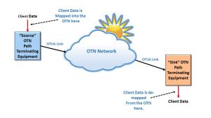
An OTU (Optical Transport Unit) frame is a data structure that an OTN Terminal (or Source STE) will use to transport its data to the outside world.

This post will call any entity that generates and transmits OTUk frames a Source STE (Section Terminating Equipment).  Likewise, we will call any entity that receives, processes, and terminates OTUk frames a Sink STE.  

In other words, as the Source STE accepts OPU/ODU frames to create an OTUk frame, it will encapsulate these OPU/ODU frames into an OTU frame by “tacking” on the OTUk overhead. 

Additionally, the Source STE will pre-condition each OTUk frame for transport over Optical Fiber by computing and appending an FEC (Forward Error Correction) field at the back end of the OTU frame and scrambling much of the OTUk frame data before converting this data into the optical domain and sending it out on Optical Fiber.  

Likewise, the OTU frame is a data structure that an OTN Terminal (or Sink STE) will accept as it receives data from the outside world.

In this case, the OTN Terminal (e.g., Sink STE) will perform the reverse functions as the Source STE.  

It will receive an optical signal from the remote STE and convert this data back into an electrical format.  Afterward, it will descramble this incoming OTUk data stream, decode the FEC field, and correct most symbol errors in the process.  

Finally, the Sink STE will terminate the OTUk data stream by extracting out the OPU/ODU frames and routing this data to downstream circuitry.  

To be clear, What do We Mean by Frame?

OTN, just like many other Networking Standards, uses framing to organize the data it transmits and receives.

Framing is a Data Link Layer function.  A transmitting terminal will organize a group of data bits into a specific data structure (called a “frame”) before transmitting it across a link.

Please see the post about the Data Link Layer for more information about the concept of Framing.

Please note that we are not talking about this kind of frame.

For OTN applications, we only transmit data that we have encapsulated into the form of an OTU frame out onto optical fiber.

OPUk and ODUk signals may be handled and processed internally (within a network element or an integrated circuit).

But we NEVER transmit OPUk and ODUk data onto the network (over optical fiber) unless we first encapsulate these signals into an OTUk frame and pre-condition this data for transport over Optical Fiber.

OTN Section and Path Terminating Equipment

In the OTN arena, we will often state that OTN Section Terminating Equipment (STE) is the entity that is responsible for transmitting and receiving OTUk frames.

We will also state that OTN Path Terminating Equipment (PTE) handles and processes ODUk frames.

Please see the posts for OTN Section Terminating Equipment (STE)and OTN Path Terminating Equipment (PTE) to understand the differences between these two types of equipment.

The OTUk Frame Format

Figure 1 illustrates the format for the standard ITU-T G.709-compliant OTU Frame.

OTUk Frame - Byte Format

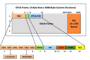
Figure 1, Illustration of the Format of the ITU-T G.709-Compliant OTU Frame

This figure shows that an OTU Frame is a 4-Byte-Row by 4080-Byte-Column Structure.  Hence, each OTU Frame consists of (4 x 4080 =)16,320 bytes.

Please note that all OTU Frames (whether an OTU1, OTU2, OTU3, or OTU4 frame) are all the same size; therefore, each frame has exactly 16,320 bytes.

NOTE:  Since each of these OTU frames are the same size (regardless of whether we are talking about an OTU1, OTU2, OTU3, or OTU4), we will, from here on, refer to these OTU frames as OTUk frames.

The Fields within an OTUk Frame

Let’s talk about the various fields within an OTUk frame.

Some of the fields in the OTUk frame have the following labels.

  • FAS
  • MFAS
  • OTUk OH
  • FEC
  • ODUk Frame

I will briefly define each of these bytes below.

FAS – Framing Alignment Signal field

The Framing Alignment Signal field occupies the first 6 bytes within an OTUk Frame.

The first three bytes (which we sometimes call the OA1 bytes) each have a fixed value of 0xF6.

The remaining three bytes (in the FAS field), which we sometimes call the OA2 bytes, each have a fixed value of 0x28.

The purpose of the FAS bytes is to provide the remote receiving OTN terminal (e.g., the Sink STE) with this fixed pattern so that it will “know” that it is receiving the first bytes of a new OTUk frame.

The Sink STE will parse through its incoming OTUk frame data stream.  As it does this, it will search for the occurrence of three consecutive bytes (each with the value 0xF6) followed by another set of three successive bytes (each with the value 0x28).

The Sink STE will rely on these FAS bytes to acquire and maintain framing alignment/synchronization with the incoming stream of OTUk frames.

If the Sink STE repeatedly fails to acquire and maintain framing alignment/synchronization with this incoming stream of OTUk frames, it will declare the dLOF (Loss of Frame) defect condition.  

MFAS – Multi-Frame Alignment Signal byte

The MFAS byte occupies the 7th byte within an OTUk frame and “resides” immediately after the FAS bytes.

Unlike the FAS bytes, the MFAS byte’s value is not fixed, as I will explain here.  

A given Source STE will transmit OTUk frames in groups of Multi-frames.

Each of these multi-frames consists of 256 consecutive OTUk frames.

Whenever a Source STE transmits the first OTUk frame (of a given Multi-frame), it will designate this particular frame as the first frame (of this multi-frame) by setting its MFAS byte field to 0x00.

When the Source STE transmits the next OTUk frame, it will set the MFAS byte (within that particular OTUk frame) to 0x01, and so on.

As the Source STE transmits each OTUk frame, it will increment the value assigned to the MFAS byte field until it reaches the value 0xFF (or 255 in decimal format).

The Source STE will then start over with transmitting a new multi-frame and set the MFAS of this next OTUk frame to 0x00, and the process repeats indefinitely.

The MFAS is a significant byte for a receiving OTN terminal (e.g., Sink STE) to keep track of because other data (such as the TTI – Trail Trace Identifier message – that is transmitted via some of the additional overhead bytes across multiple OTUk frames).

The Source STE will align the transmission of these particular messages (e.g., the SM-TTI messages, PM-TTI messages, PSI Messages, etc.) with the MFAS byte as it transports these messages via the OTUk data stream.

Please see the relevant posts on SM-TTI (Section Monitoring – Trail Trace Identifier) Messages, PM-TTI (Path Monitoring – Trail Trace Identifier) Messages, and PSI (Payload Structure Identifier) Messages to learn more about these types of messages.  

ODUk Frame

The ODUk Frame “portion” of the OTUk frame is all the remaining data (which resides within the OTUk frame) that is not considered an OTUk Overhead field.  This includes all bytes within the ODU (Optical Data Unit) and, in turn, OPU (Optical Payload Unit) within the OTUk frame.  Please see the posts for ODUk and OPUk to learn more about those parts of the OTUk frame.

FEC – Forward Error Correction

ITU-T G.709 specifies that OTUk frames should include an FEC (Forward Error Correction) field that contains the Reed-Solomon RS (255,239) FEC codes.

NOTE:  I discuss the RS(255,239) FEC code in detail in Lesson 9, within THE BEST DARN OTN TRAINING PRESENTATION…PERIOD!!!

The FEC field permits a Sink STE to detect and correct many symbol (or byte) errors that may have occurred during transmission.

ITU-T G.709 indicates that using FEC is optional for OTU1, OTU2, and OTU3 applications.  

However, the use of FEC is mandatory for OTU4 applications.  

Please see the OTUk FEC discussion within Lesson 9 of THE BEST DARN OTN TRAINING PRESENTATION…PERIOD!!  for more information about this field.

New Comprehensive OTN Training…Available Now. Click on the Banner Below to Learn More!!!

Discounts Available for a Short Time!!!

The Rest of OTUk OH (Overhead) fields

The remaining OTUk OH fields consist of the following three fields for a total of seven (7) bytes:

  • SM Field
  • GCC0 Field
  • OSMC (OTN Synchronizing Messaging Channel) Field
  • RES (Reserved) Field

We will briefly describe each of these fields below.

SM (Section Monitoring) Field (3 bytes)

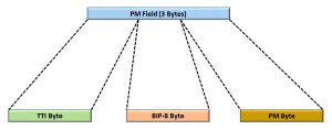
Figure 2 shows the byte format for the Section Monitoring or SM Field.

OTU - SM (Section Monitoring) Field, TTI Byte, BIP-8 Byte, SM Byte

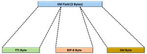
Figure 2, Byte-Format of the SM (Section Monitoring) Field

This figure shows that the SM Field consists of the following three bytes:

  • TTI – Trail Trace Identifier Byte
  • BIP-8 Byte
  • SM Byte

Below, we will describe each of the bytes (within the SM field).  We also discuss these fields in much greater detail in their respective posts.

TTI – Trail Trace Identifier Byte

This byte-field carries the 64-byte Section Monitoring Trail-Trace Identifier message.  Since there is only one TTI byte within each OTUk frame, the OTN Transmitter (or Source STE) will transmit 64 OTUk frames to send the entire 64-byte Trail Trace Identifier message.

Please see the Section Monitor-Trail Trace Identifier post to learn how we use this identifier in an OTN system.

BIP-8 (Section Monitoring BIP-8) Byte

The Source STE will perform a BIP-8 calculation over the entire OPUk frame within its corresponding OTUk frame.

Afterward, the Source STE will insert the results of this BIP-8 calculation into the SM-BIP-8 byte field of the outbound OTUk frame two frame periods later.

Finally, the remote Sink STE will use this BIP-8 calculation to check for bit errors during transmission.

Please see the Section Monitoring BIP-8 post for more information about how we compute and use this byte field in an OTN system.

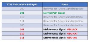
SM (Section Monitoring) Byte

Figure 3 presents the bit format for the Section Monitoring Byte (not to be confused with the 3-byte SM field).

OTU Frame - Section Monitoring Byte Format - Optical Transport Networks

Figure 3, Bit Format of the Section Monitoring Byte

This figure shows that the SM Byte consists of the following bit fields:

  • BEI/BIAE (4 bits)
  • BDI (1 bit)
  • IAE (1 bit)
  • RES – Reserved (2 bits)

We will briefly describe each of these bit-fields below.

BEI/BIAE – Section Monitoring – Backward Error Indicator (BEI) or Backward Incoming Alignment Error (BIAE) – (4 bits)

The purpose of the BEI/BIAE nibble-field is two-fold.

  • To permit the Source STE to provide the remote Sink STE (at the far-end) with feedback on the number of SM-BIP-8 errors that the near-end (local) Sink STE is detecting within its incoming OTUk data stream.
    • The Source STE will set the BEI/BIAE nibble-field (within each outbound OTUk frame) to the SM-BEI (Backward Error Indicator) value.  
  • And to permit the Source STE to alert the remote Sink STE (again, at the far-end) that the near-end (local) Sink STE is declaring the dIAE defect condition.
    • The Source STE will accomplish this by setting the BEI/BIAE nibble-field to the value of “1011”, which carries the BIAE (Backward Input Alignment Error) Indicator.  

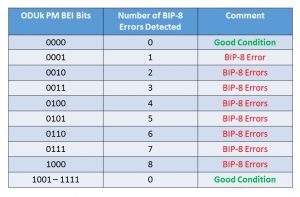
Table 1 presents the range of values that the Source STE can set the BEI/BIAE Nibble-field, within its outbound OTUk frames, for each of the conditions mentioned above. 

Table 1, How to Interpret the Section Monitoring BEI/BIAE bit-fields

OTUk SM_BEI/BIAE Nibble-ValueSink STE declaring the dIAE Defect?Number of SM-BIP-8 Errors DetectedComments
0000NO0Good Condition
0001NO1BIP-8 Error
0010NO2BIP-8 Errors
0011NO3BIP-8 Errors
0100NO4BIP-8 Errors
0101NO5BIP-8 Errors
0110NO6BIP-8 Errors
0111NO7BIP-8 Errors
1000NO8BIP-8 Errors
1001, 1010NO0Good Condition
1011YES0BIAE Indicator
1100 to 1111NO0Good Condition

Please see the Section Monitoring Error/Defect post to learn more about these defect and error conditions.

BDI – Section Monitoring – Backward Defect Indicator Bit Field

The purpose of the BDI bit-field is to permit the Source STE to alert the remote (far-end) Network Element that the local (near-end) Sink STE is declaring a service-affecting defect.  

This Source STE will set this bit-field to “0” or “1” depending upon whether the local (near-end) Sink STE is declaring a service-affecting defect condition (at the OTUk-layer), as I describe below.

0 – The Source STE will set the BDI bit-field to “0” if the near-end Sink STE is NOT declaring a service-affecting defect condition.

1 – The Source STE will set the BDI bit-field to “1” if the near-end Sink STE is currently declaring a service-affecting defect condition.

Please see the OTUk-BDI post to learn more about the BDI defect condition.

IAE – Section Monitoring Incoming Alignment Error Bit-Field

The Source STE will set this bit-field to “0” or “1” depending upon whether the upstream circuitry detects a frame-slip event within an ODU signal that we are ultimately mapping into this particular OTUk data stream (that this Source STE is transmitting downstream).

0 – Indicates that upstream circuitry is NOT detecting any frame-slip events (within the ODU signal we are mapping into this particular OTUk signal).   The Source STE will set the IAE bit-field to “0” (within its outbound OTU data-stream) to denote this good condition.

1 – Indicates that upstream circuitry is currently detecting a frame-slip event (within the ODU signal we are mapping into this particular OTUk signal).  The Source STE will set the IAE bit-field to “1” (within its outbound OTU data-stream) to denote this abnormal condition.

I present detailed information on the IAE bit-field within Lesson 9 of THE BEST DARN OTN TRAINING PRESENTATION…PERIOD!!.

GCC0 – General Communication Channel # 0 – (2 bytes)

The GCC0 is a general communications channel for proprietary communication to the System Designer/Manufacturer.

This channel is similar to the DCC (Data Communication Channels) in SONET/SDH.

Please see the GCC0 post for more information about how the System Designer/Manufacturer can use this field.

OSMC – OTN Synchronization Messaging Channel  – 1 byte

The Network User can use the OSMC channel to transport SSM (Synchronization Status Messages) or PTP (Precision Time Protocol) messages throughout the OTN.

Please see the OSMC post for more information about how the System Designer/Manufacturer can use this field.

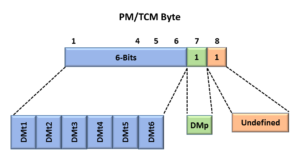
RES – Reserved (or Undefined) (1 byte)

OTUk Frame Repetition Rates and Bit Rates

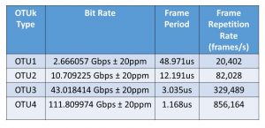
Since all speeds (or types) of OTUk signals use the same frame size, the reason that (for example) an OTU2 runs at a faster bit rate than does an OTU1 is that the frame repetition rate for an OTU2 is higher (e.g., more rapid) than that for an OTU1.

Table 2 presents the OTUk frame period and bit rate for each type of the OTUk signal.

Table 2, Frame Periods and Bit-Rate for each kind of OTUk signal

OTUk Bit Rate and OTUk Frame Period

NOTES:

  1. This post has defined the Fully Compliant OTUk frames.   It does not address the functionally standardized OTUk frames (such as the OTUkV or OTUk-v).  Please see the posts for the OTUkV and OTUk-v frames for more information on these types of frames.
  2. This post does not discuss the new OTUCn types of OTN signals.  Please see the OTUCn post for more information on these higher-speed signals.

Has Inflation got You Down? Our Price Discounts Can Help You Fight Inflation and Help You Become an Expert on OTN!! Click on the Banner Below to Learn More!!

(DISCOUNT OFFERED for a Short Time ONLY!!)

For More Information on OTN Posts in this Blog, click on the Image below.

OTN Related Blog

OTN Related Topics within this Blog

OTN Related Topics within this Blog General Topics Consequent Equations - What are they and How can you use them? ...