What is an ODTU4.1 Structure?

This post defines the ODTU4.1 (Optical Tributary Data Unit 4.1). This post also describes how we use the ODTU4.1 structure/frame whenever we are mapping/multiplexing ODU0 signals into an OPU4 signal.


What is the ODTU4.1 Frame/Structure?  And When do We use it?

Introduction

The term, ODTU4.1, is an acronym for Optical Data Tributary Unit 4.1.

A Mapper circuit will use this structure whenever mapping and multiplexing anywhere between 1 and 80 ODU0 tributary signals into an OPU4/ODU4 server signal.

We will discuss the following topics within this blog post.

  • What does the term ODTU4.1 mean?
  • A description/definition of the ODTU4.1 frame/structure.
  • How do we use the ODTU4.1 structure when mapping/multiplexing multiple lower-speed ODU0 tributary signals into an OPU4 server signal?
    • What is the timing/frequency relationship between each ODTU4.1 signal, and
    • What is the timing/frequency relationship between each ODTU4.1 signal and the outbound OPU4 frame data?

What is the meaning of the term ODTU4.1?

The numeral 4 (within the expression ODTU4.1) reflects that we use this structure to map data into an OPU4/ODU4 server signal.

The numeral 1 (again, within the expression ODTU4.1) reflects that this structure transports a single ODU0 signal (which contains only 1 (one) 1.25Gbps-unit  of bandwidth).

Therefore, the ODTU4.1 structure only transports 1 (one) 1.25Gbps-unit (or tributary-slot) of bandwidth as we map/multiplex this data into an OPU4/ODU4 server signal.

NOTE:  I have extensively discussed how we map 80 ODU0 tributary signals into an ODU4 server signal within Lesson 5/ODU4 of THE BEST DARN OTN TRAINING PRESENTATION…PERIOD!!!

There are other similar structures, such as the ODTU4.2, ODTU4.8, ODTU4.31, and ODTU4.ts frames, that we will use to map an ODU1 (2 time-slots), ODU2/2e (8 time-slots), ODU3 (31 time-slots) and ODUflex (ts time-slots) into an OPU4 signal, respectively.

We will discuss each of these structures in other posts.

When do we use the ODTU4.1 structure?

We use these structures when mapping and multiplexing from 1 to 80 lower-speed ODU0 tributary signals into an OPU4/ODU4 server signal.

ITU-T G.709 states that whenever we map/multiplex some ODU0s into an OPU4/ODU4 signal, then we need to do this by executing the following four-step process.

  • Convert each ODU0 signal into an Extended ODU0 signal.
  • GMP map each ODU0 signal into its ODTU4.1 structure/signal, and
  • Byte-Wise Multiplex as many as 80 ODTU4.1 signals together and then
  • Load this data into the OPU4 Payload area.

ITU-T G.709 presents a series of figures on mapping/multiplex lower-speed ODUj tributary signals into a higher-speed OPUk server signal (e.g., k > j).

The standard presents the following figure on how to map/multiplex ODU0 signals into an OPU4.

ITU-T G.709 using ODTU4.1 to map ODU0s into an OPU4

Figure 1, Illustration of the ITU-T G.709 Drawing on how to Map/Multiplex up to 80 ODU0s signals into an OPU4 signal.  

I (more or less) copied Figure 1 straight out of ITU-T G.709.

I added some additional text to explain this figure and ITU-T G.709’s instructions.

Figure 1 states that we must first map a single “Extended ODU0 signal” into a single ODTU4.1 signal using GMP (Generic Mapping Procedure).

What Do We Mean by an Extended ODU0 Signal?

Before we can begin the process of mapping/multiplexing any ODU0 tributary signals into an OPU4/ODU4 server signal, we must first convert each of these ODU0 signals into an Extended ODU0 signal.

This means we need to take an ODU0 frame and then “extend it” by attaching the FAS and MFAS fields to this frame, as shown below in Figure 2.

Extended ODUk Framing Format

Figure 2, Illustration of the Extended ODU0 Framing Format

We attach the FAS and MFAS fields to each of these ODU0 frames so that the Sink PTE circuitry (at the remote end of the fiber link) can locate the boundaries of ODU0 frames as it de-maps this data from the ODTU4.1 structures.

Please see the OTU Post for more information on the FAS and MFAS fields.

Please also note that (as we include the FAS and MFAS fields within the ODU0), we fill in the rest of the OTUk Overhead to an all-zeroes pattern, and we don’t append the FEC to the back-end of the ODU0 frame.

Mapping the Extended ODU0 signals into the ODTU4.1 Signal/Structure

Once we have converted each of the ODU0 signals into Extended ODU0 signals, we will proceed to GMP map this data into the ODTU4.1 signal/structure.

After performing this mapping step, we will (from here on) be working with ODTU4.1 signals (instead of ODU0 signals) as we load this data into an OPU4/ODU4 frame structure and transport it across an optical link.

These ODU0s will remain embedded within this ODTU4.1 data stream until some “ODTU4.1 to ODU0 De-Mapper” circuit de-maps/extracts the ODU0 signals from the ODTU4.1 signals.

If we are mapping/multiplexing 80 ODU0 signals into an OPU4 signal, then we will map 80 ODU0 signals into each of their own 80 ODTU4.1 signals in parallel.

And we will then have 80 separate ODTU4.1 signals to process and manipulate.

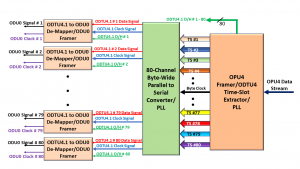
Figure 4 (further down in this post) illustrates some “Mapping circuitry” that maps 80 ODU0 signals into 80 ODTU4.1 signals in parallel.

Byte-Wise Multiplexing the ODTU4.1 Data into the ODTUG4 Structure

Next, Figure 1 states that we must byte-wise multiplex each of the 80 ODTU4.1 signals into a single ODTUG4 data stream.

And finally, we should then map (or insert) this ODTUG4 data stream into the OPU4/ODU4 server payload.

What does the ODTU4.1 Structure Look Like?

Figure 3 presents an illustration of the ODTU4.1 Framing Format.

ODTU4.1 Frame Format

Figure 3, Illustration of the ODTU4.1 Frame Format

This figure shows that the ODTU4.1 Frame consists of two different sections.

  • The ODTU4.1 payload area and
  • The ODTU4.1 overhead area

Figure 3 also shows that the ODTU4.1 payload is a 160 Row x 95 Byte Column structure.  This figure also shows that the ODTU4.1 frame comprises 6 bytes of overhead.

Please note that 160 Rows x 95 Byte Columns = 15,200 Bytes.

This means that the payload portion of each ODTU4.1 frame will carry 15,200 bytes (the exact number of payload bytes each OPU4 frame takes).

What kind of data resides within the ODTU4.1 Payload?

In short, the ODTU4.1 Payload will contain the contents of its respective Extended ODU0 signal.

Whenever we are GMP mapping an Extended ODU0 signal into an ODTU4.1 signal, we will load the entire Extended ODU0 data stream (e.g., ODU0 overhead, FAS field, and payload data) into the ODTU4.1 payload.

We will load this data into the ODTU4.1 payload in the standard transmission order.

What kind of data resides within the ODTU4.1 Overhead?

When the Mapper circuitry GMP maps the Extended ODU0 tributary signal into the ODTU4.1 structure, it will compute and generate some GMP parameters (for this particular mapping operation).

The Mapper circuitry will compute these GMP parameters based upon the exact bit rates of the Extended ODU0 signal and that on the ODTU4.1 (Server) signal.

The Mapper circuitry will then load this GMP mapping data into the JC1 through JC6 fields (within the ODTU4.1 overhead), just as a GMP mapper would for any client signal.

This set of JC1 through JC6 fields serves the same roles as the JC1 through JC6 fields (within an OPUk structure) whenever we use GMP mapping.

How do we transport the ODTU4.1 Overhead and Payload data across the Optical Link (within an OTN)?

Please see the OMFI Post for details.

Are all the ODTU4.1 signals both frame and byte-synchronous with each other whenever we map this data into the OPU4 payload?

In short, the answer is “Yes.”

The ODTU4.1 frames and signals must have the following timing/synchronization characteristics.

  • Each of the 80 ODTU4.1 signals must be bit-synchronous with each other.
  • These ODTU4.1 signals must also be bit-synchronous with the outbound OPU4/ODU4 data stream.
  • Each of the 80 ODTU4.1 signals must be frame-synchronous with each other, and
  • All 80 ODTU4.1 signals must be frame synchronous with the 80 OPU4 Frame Superframe they will eventually be multiplexed into.

We will discuss these characteristics (of the ODTU4.1 signals) below.

BUT FIRST – What about the timing and requirements of the ODU0 tributary signals?

Each ODU0 tributary signal (that we are mapping into an OPU4/ODU4 server signal) can be utterly asynchronous to each other.

Additionally, the only absolute timing requirement for the ODU0 signals is that they have to comply with the Frequency Tolerance requirements per ITU-T G.709.

There is also no requirement that these 80 ODU0 tributary signals be frame-aligned with each other either.

However, once the ODU0 signals are each GMP mapped into their ODTU4.1 signal, then each of the ODTU4.1 signals MUST be both byte- and frame-synchronous to each other.

Each of these ODTU4.1 signals must also be bit-synchronous with the outbound OPU4/ODU4 server signal.

Additionally, each of these ODTU4.1 frames must be aligned with the 80 OPU4 frame Superframe (that they will eventually be a part of).

GMP mapping addresses the timing differences between each of the individual ODU0 tributary signals as they transition from the “ODU0 tributary signal time domains” to the “ODTU4.1/OPU4 Time Domain”.

All of this means that the ODU0 to OPU4 Mapper Circuit must ensure that “Byte 1” (the very first payload byte) within each of the 80 ODTU4.1 frames are all being applied to the “ODTU4.1 Byte MUX” simultaneously.

Let’s focus on these points in greater detail.

ODTU4.1 Signals being Bit-Synchronous with each other

Figure 4 illustrates an ODU0 tributary signal to OPU4 Mapper circuit.

This figure presents 80 sets of “ODU0 Frame Extender/ODU0 to ODTU4.1 Mapper” blocks.

Each block is responsible for GMP mapping its ODU0 signal into an ODTU4.1 Data Signal.

ODU0 to OPU4 Mapper Circuit

Figure 4, Illustration of an ODU0 tributary signal to OPU4 Mapper Circuit

Figure 4 also shows that a single clock source (e.g., ODTU4.1 and OPU4 Clock Source) will function as the timing source for each of the 80 ODU0 Frame Extender/ODU0 to ODTU4.1 Mapper blocks.

This means that each of the resulting ODTU4.1 signals will be generated based on and synchronized with a common clock source (e.g., the ODTU4.1 and OPU4 Clock Source, in this case).

The OPU4 Output signal will also use the ODTU4.1 and OPU4 Clock Source as its timing source.

ODTU4.1 Signals are Byte-Aligned with Each Other

Figure 5 illustrates an abbreviated byte stream for each of the 80 ODTU4.1 payload signals.

80 ODTU4.1 Byte Data Streams

Figure 5, Illustration of the Byte Streams for each of the 80 ODTU4.1 Signals (output from the ODU0 Frame Extender/ODU0 to ODTU4.1 Mapper block in Figure 4).

This figure shows that each ODU0 Frame Extenders/ODU0 to ODTU4.1 Mapper circuit must simultaneously generate and transmit the first payload byte of their ODTU4.1 frame.

Likewise, each ODU0 Frame Extender/ODU0 to ODTU4.1 Mapper circuits must all generate and transmit the very second payload byte of their ODTU4.1 frame simultaneously, and so on.

All 80 of these byte streams will then be routed to downstream circuitry, which will byte-multiplex and map this data into the OPU4 payload, as shown below in Figure 6.

Byte Wise Multiplexing 80 ODTU4.1 Signals into the OPU4 Payload

Figure 6, Simple Illustration of Circuitry Byte-Wise Multiplexing Each (of 80) ODTU4.1 Signals into an OPU4 Payload.  

ODTU4.1 Signals MUST be Frame Aligned to the 80 OPU4 Frame Superframe

In the OMFI post, we mentioned that we would ultimately map and multiplex each of the ODTU4.1 signals into an 80 OPU4 Frame Superframe.

Figure 7 illustrates an 80 OPU4 frame Superframe we created by byte-wise multiplexing these 80 ODTU4.1 data streams together.

Full OPU4 Superframe

Figure 7, Illustration of an 80 OPU4 frame Superframe.

Looking at Row 1, Byte-Column 17 within OPU4 Frame # 1, you will see that we have designated this byte-field as “1-1“.

This designation means that this byte originated from ODTU4.1 Signal # 1 and is the very first byte (e.g., byte # 1) within that particular ODTU4.1 frame.

Likewise, we designated the next byte-field (to the right) as “2-1“.

This means that this byte originated from ODTU4.1 Signal # 2 and that it is the very first byte within that particular ODTU4.1 frame, and so on.

Figure 6 also shows that the very first payload byte (within the 80 OPU4 frame Superframe) is the very first payload byte (within an ODTU4.1 frame) that originates from ODTU4.1 Signal # 1 (e.g., byte-field “1-1“).

This figure also shows that the next 79 bytes (within this OPU4 frame) are the very first bytes (within each of their ODTU4.1 frames) originating from ODTU4.1 Signal # 2 through ODTU4.1 # 80.

We have designated the next 79 bytes as “2-1“, “3-1“, and so on, all the way to “80-1“.

This figure reinforces the fact that each of the ODTU4.1 streams must also be frame-aligned with each outbound 80 OPU4 frame Superframe.

To better appreciate these concepts, I strongly recommend you check out this portion of Lesson 5 within THE BEST DARN OTN TRAINING..PERIOD course.  

Has Inflation got You Down? Our Price Discounts Can Help You Fight Inflation and Help You Become an Expert on OTN!! Click on the Banner Below to Learn More!!!

Discounts Available for a Short Time!!!

For More Information on OTN Posts in this Blog, click on the Image below.

OTN Related Blog

OTN Related Topics within this Blog

OTN Related Topics within this Blog General Topics Consequent Equations - What are they and How can you use them? ...

What is the OMFI Field?

This post defines the acronym OMFI (OPU Multi-Frame Indicator). It also describes when and how we use the OMFI field in OTN (Optical Transport Network) applications.

What is the OMFI (OPU Multi-Frame Indicator) Field?

Introduction

OMFI is an acronym for “OPU Multi-Frame Indicator.”

We use the OMFI field when mapping/multiplexing multiple lower-speed ODUj tributary signals into an ODU4 server signal (where j ranges from 0 through 3 and can include flex or 2e).

Whenever we are mapping/multiplexing these lower-speed ODUj tributary signals into an OPU4 server signal, we will do so on an 80 OPU4 frame Superframe basis.

As we map and multiplex these lower-speed ODUj tributary signals into an OPU4 signal, we will create as many as 80 sets of GMP Mapping Parameter for each Superframe.

At the Source PTE (Path Terminating Equipment), the ODUj to OPU4 Mapper Circuit will insert each of these 80 GMP Mapping Parameters into the Overhead Fields of the 80 consecutive OPU4 frames within each Superframe.

The payload portions of each of these OPU4 frames will contain multiplexed ODTU4.ts data (e.g., ODTU4.1, ODTU4.2, ODTU4.8, ODTU4.31, or ODTU4.ts data-streams).

The Source PTE will transmit these OPU4 frames to the Sink PTE (at the other end of the path).

At the Sink PTE, the OPU4 to ODUj De-Mapper circuit will need to know which set of GMP Parameter data pertains to which ODTU4.ts data-stream to properly de-map out these ODUj tributary signals from these ODTU4.ts signals, within the incoming OPU4 signal.

The de-mapper will use the OMFI field (within each OPU4 frame) to figure this out.

We will explain this concept in greater detail later on in this blog.

Where is the OMFI field located?

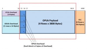
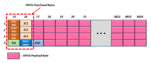
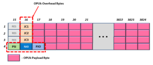
If we are dealing with an OPU4 frame, the OMFI field will reside within the OPU4 Overhead in Row # 4 and Column Byte # 16.

Figure 1 shows a drawing of an OPU4 frame in which we highlight the location of the OMFI field.

OMFI Location
Figure 1, Location of the OMFI field within the OPU4 Frame

The OMFI field does not exist in OPUk frames for any other rates.  The OMFI field only exists within the OPU4 frame.

In other words, OPUflex, OPU0, OPU1, OPU2, OPU2e, and OPU3 frames will NOT have an OMFI field.

When would we use the OMFI field?

We will only use the OMFI field if mapping/multiplexing some lower-speed ODUj tributary signals into an OPU4 server signal.

In other words, we would use the OMFI field if we wish to perform any of the following mapping/multiplexing operations:

  • 80 ODU0 tributary signals into an OPU4
  • 40 ODU1 tributary signals into an OPU4
  • 10 ODU2 (or ODU2e) tributary signals into an OPU4
  • 2 ODU3 tributary signals into an OPU4
  • Various combinations of rates/number of ODUflex tributary signals into an OPU4 server signal

Further, we can also use the OMFI field if we are mapping/mapping multiple combinations of rates of ODUflex signals along with the appropriate number of other ODUj tributary signals (where j can be 0, 1, 2/2e, or 3) into an OPU4 server signal.

NOTE:  We do NOT use the OMFI field if we map some non-OTN client signals (such as 100GbE/100GBASE-R) into an OPU4 signal.

So What does the OMFI field do?

The OMFI field is a byte-wide counter that counts from 0 to 79 and then overflows back to 0 repeatedly.

More specifically, a piece of OTN Network Equipment (e.g., the Source PTE) will (at some point) transmit an OPU4 frame with the OMFI field set to the value “0x00”.

When the Source PTE transmits the next OPU4 frame, it will set its OMFI byte-field to 0x01.   The Source PTE will increment the value that it writes into the OMFI byte-field within each OPU4 frame it generates and transmits.  

Eventually, the Source PTE will transmit an OPU4 frame with the OMFI field set to the value 0x4F (which is the number 79 in decimal format).

Afterward, when the Source PTE transmits the next OPU4 frame, it will set the OMFI field back to 0x00, and it will continue to send another set of 80 consecutive OPU4 frames in this manner, repeatedly.

This means that the OTN network can (and does) use the OMFI field to group 80 consecutive OPU4 frames into an OPU4 Superframe.

We will discuss these OPU4 Superframes later on in this post.

Clueless about OTN? We Can Help!!! Click on the Banner Below to Learn More!!!

Corporate Discounts Available!!!

Why can’t we use the MFAS field for OPU4 Applications?

This is a good question.

The MFAS field (like the OMFI field) is a byte-wide counter.  The behavior and function of these two bytes are very similar.

NOTE:  Please see the OTUk Post for more information about the MFAS field.

The Source STE increments the value within the MFAS byte as it transmits each new OTUk frame.

However, the OMFI byte-field only counts from 0 to 79, and then it overflows back to 0 and then repeats the process.

The MFAS byte counts from 0 to 255, overflows back to 0 and then repeats the process indefinitely.

The MFAS field is convenient for grouping 256 consecutive OTUk/ODUk/OPUk frames into a 256-frame Superframe.

It is also suitable for grouping 4, 8, 16, and 32 consecutive OPUk frames in smaller Superframes. 

NOTE:  We use the MFAS byte when mapping/multiplexing lower-speed ODUj tributary signals into ODU1, ODU2, or ODU3 server signals.  

In short, the MFAS is great for grouping OPUk frames into Superframes with sizes of 2n consecutive OPUk frames (e.g., 22 = 4, 23 = 8, 24 = 16, 25 = 32, and so on).

However, no integer value for n (within the expression 2n) will give you a value of 80.

Thus, if I want to group 80 ODU4 frames into an ODU4 Superframe, the MFAS byte is useless for that purpose.

We need a different byte for this role.  This is why we have the OMFI byte field.

Would we use the OMFI field for the AMP (Asynchronous Mapping Procedure)?

In a word, “No.”

When mapping client signals into an ODU4 server signal, we will ONLY use the GMP (Generic Mapping Procedure).

We never use AMP to map client signals into an OPU4 payload.  This is NOT allowed per ITU-T G.709.

NOTE:  This statement is true, whether we are mapping non-OTN client data (such as 100GBASE-R) or lower-speed ODUj tributary signals into an OPU4 signal.

To be clear, we can use AMP to map client signals into OPU1, OPU2, and OPU3 server signals but not into an OPU4 server signal.

This is a good trick question, however.

This is a trick question because if we were using AMP to map client data into an OPUk frame, then the NJO (Negative Justification Opportunity) byte would occupy the same byte position that the OMFI field occupies for OPU4 applications.

NOTE:  Please see the AMP (Asynchronous Mapping Procedure) post for more information on the NJO byte.

How do we use the OMFI field in a system application?

Let’s assume we wish to map and multiplex 80 ODU0 tributary signals into an OPU4 server signal.

If we want to do this, ITU-T G.709 states that we should perform this mapping/multiplexing in a five-step process.

  • Convert each ODU0 signal into an Extended ODU0 signal.
  • Use GMP to map each of the 80 ODU0 signals into their ODTU4.1 structure/signal.  This step will create 80 ODTU4.1 signals.
    • As we perform this task, we will create 80 sets of GMP Mapping parameters that we will load into the Overhead Portion of 80 sets of ODTU4.1 frames.  
  • Byte interleaves all 80 of the payload portion of these ODTU4.1 signals together into a single data stream.
  • Load this byte-interleaved ODTU4.1 payload data into the OPU4 payload within each outbound OPU4 frame.
  • Load the GMP mapping parameters (within the ODTU4.1 Overhead) into the OPU4 overhead.  

Please see the Extended ODUj Post for more details on the Extended ODU0 signal.

What is an ODTU4.1 Frame/Signal?  

The standards define the ODTU4.1 as Optical Data Tributary Unit (for an OPU4/ODU4 server signal) with 1 (one) Time-Slot.

For this post, I will state that the ODTU4.1 structure/signal is an intermediate frame/signal (defined in ITU-T G.709). 

We only use this frame/signal whenever mapping/multiplexing ODU0 tributary signals into an OPU4 signal.

We present a more thorough description of the ODTU4.1 structure in another post.

Figure 2 shows a drawing of a Mapper Circuit that performs this two-step Mapping/Multiplexing Process.

ODU0 to OPU4 Mapper Circuit

Figure 2, Illustration of an 80 ODU0 Signal to OPU4 Mapper Circuit

Whenever we GMP map a given ODU0 signal into an ODTU4.1 structure, the Mapper circuit will compute the resulting GMP parameters for this single mapping operation.

What’s the Deal with the Number 80?

Since we individually map each of the 80 ODU0 tributary signals into their ODTU4.1 structure, and since each of the 80 ODU0 signals CAN be asynchronous to the remaining 79 ODU0 signals, there will be 80 unique sets of GMP mapping parameters within this OPU4 signal.

The ODU0 to OPU4 Mapper circuit will need to insert each of these 80 sets of GMP parameters into the OPU4 data stream to provide the OPU4 to ODU0 De-Mapper circuit (at the remote Sink PTE) with the GMP Justification Control information that it needs to be able to properly de-map out each of the ODU0 tributary signals from their ODTU4.1 signal.

Has Inflation got You Down? Our Price Discounts Can Help You Fight Inflation and Help You Become an Expert at OTN!!! Click on the Banner Below to Learn More!!!

Discounts Available for a Short Time!!!

So, where does the Mapper Circuit insert the GMP parameters (for all 80 ODU0s) into the OPU4 Frame?

I mentioned earlier that when mapping lower-speed ODUj tributary signals into an OPU4 signal, we execute this procedure by creating an 80 OPU4 frame Superframe.

In other words, as we map and multiplex these 80 ODU0 signals into the OPU4 signal, we will also create these 80 OPU4 frame Superframes.

In the OPU Post, I stated that each OPUk frame consists of an OPUk Payload and OPUk Overhead.

Thus, an 80 OPU4 frame Superframe will contain 80 sets of OPU4 payload and will also include 80 sets of OPU4 overhead.

Please note that each of these OPU4 Superframes contains 80 frames and we are trying to map 80 ODU0s into an OPU4 is NOT a coincidence.

This was all done by design.

ITU-T G.709 states that an ODU0 to OPU4 Mapper circuit should insert the GMP parameters (that we obtained when we GMP mapped ODU0 # 1 into its ODTU4.1 frame/signal) into the JC1 through JC6 bytes within the Overhead of OPU4 Frame # 1 (within the 80 OPU4 Frame Superframe).

Likewise, the standard also states that the Mapper should insert the GMP parameters (we obtained when we mapped ODU0 # 2 into its ODTU4.1 frame/signal) into the JC1 through JC6 bytes within the Overhead of OPU4 Frame # 2.

This process should continue to OPU4 Frame # 80.

At this point, the ODU0 to OPU4 Mapper circuit has completed its transmission of an 80 OPU4 Frame Superframe, and it should start transmitting a new Superframe by sending OPU4 Frame # 1 again (and so on).

But How Do We Know Which OPU4 Frame is OPU4 Frame # 1, # 2, and so on?

The short answer is the contents of the OMFI byte of each of these OPU4 frames.

Whenever the OMFI byte (within a given OPU4 frame) is set to “0x00”, we can state that this particular OPU4 Frame is the first frame in the 80-frame Superframe.

Hence, we can designate this frame as OPU4 Frame # 1.

Likewise, whenever the OMFI byte (within a given OPU4 frame) is set to “0x01”, we can state that this particular OPU4 frame is the second frame in the 80-frame Superframe.

Thus, we can designate this frame as OPU4 Frame # 2, and so on.

We Use the OMFI Byte to Identify Each of these 80 OPU4 frames.

Therefore, if the Sink PTE (at the remote end) receives an OPU4 frame, in which the OMFI byte is set to “0x00”, then we know the following things about the overhead data within that frame.  We understand that the data (within the JC1 through JC6 bytes) will contain the GMP parameter data we obtained when the Source PTE mapped ODU0 # 1 into its ODTU4.1 frame/signal.

Likewise, if the Sink PTE receives an OPU4 frame, in which the OMFI byte is set to “0x01”, we know the following about the overhead data within this frame.  We understand that the data (within the JC1 through JC6 bytes) will contain the GMP parameter data we obtained when the Source PTE mapped ODU0 # 2 into its ODTU4.1 frame/signal.

And so on, for the remaining 78 frames within this OPU4 frame Superframe.  

Figure 3 presents an abbreviated drawing of an 80 OPU4 Frame Superframe.

This figure also shows some helpful information about the contents of the Overhead data within each of the OPU4 frames. 

More specifically, this drawing also identifies which ODU0 to ODTU4.1 frame GMP mapping operation these overhead fields pertain to within each OPU4 frame.

80 OPU4 Frame Superframe

Figure 3, Illustration of an 80 OPU4 Frame Superframe

For example, for OPU4 Frame 1, some red text states the following:  “GMP Mapping Data associated with ODTU4.1/ODU0 # 1″. 

This text means that the six Justification Control bytes (e.g., the JC1 through JC6 byte – in the Pink Fields) contain the GMP mapping parameters that the Source PTE generated when it GMP mapped ODU0 # 1 into ODT4.1 signal # 1.    

This is handy information for the Sink PTE.  

So what does the De-Mapper Circuit do?

As the De-Mapper circuit (within the remote Sink PTE) receives and processes these OPU4 frames, it will need to execute the following two-step procedure to properly de-map and recover these ODU0 tributary signals from this incoming OPU4 data stream.

  • Byte de-interleaves the OPU4 payload data into 80 parallel streams of these ODTU4.1 signals.
  • Use GMP to de-map each ODU0 signal from their ODTU4.1 signal (e.g., de-map 80 ODU0 signals out of 80 ODTU4.1 signals)

I show an illustration of an OPU4 to 80 Channel ODU0 De-Mapper circuit below in Figure 4.

OPU4 to ODU0 De-Mapper Circuit

Figure 4, Drawing of an OPU4 to 80 Channel ODU0 De-Mapper Circuit

De-Mapping the ODU0 Signal from Each ODTU4.1 Signal

However, for the de-mapper circuit (within the Sink PTE) to do this successfully, it will need to have the correct GMP mapping parameters that the Source PTE created at the remote end. 

In other words, for the Sink PTE to de-map out ODU0 # 1 from ODTU4.1 signal # 1, it will need to have the same GMP mapping parameters that the Source PTE (at the remote end) generated when it mapped ODU0 # 1 into ODTU4.1 signal # 1, in the first place.  

Likewise, for the Sink PTE to de-map out ODU0 # 2 from ODTU4.1 signal # 2, it will need to have the same GMP mapping parameters that the Source PTE (again, at the remote end) generated when it mapped ODU0 # 2 into ODTU4.2 signal # 2.  

The Sink PTE will receive 80 sets of GMP mapping parameters within each 80 Frame OPU4 Superframe.  

How does the Sink PTE know which (of the 80) GMP mapping parameters to use if we wish to de-map out ODU0 # 1 from ODTU4.1 signal # 1?  

Answer:  It needs to use the overhead data within the OPU4 frame, in which the OMFI byte is set to 0x00.

Thus, the de-mapper circuit must rely on the OMFI value to keep this information straight.

In other words, the Sink PTE will use the OMFI byte to properly marry up each of the 80 GMP mapping parameters (within the incoming OPU4 data stream) with 80 ODTU4.1 data streams.  

Hence, using the OMFI byte, the Sink PTE will be able to correctly de-map out all 80 ODU0 signals from each of their ODTU4.1 signals that we extract from the incoming OPU4 data stream.  

Does ITU-T G.798 Define any Defects that Pertain to the OMFI field?

Yes, ITU-T G.798 does define the dLOOMFI (Loss of OMFI Synchronization) defect for applications in which we are mapping and multiplexing lower-speed ODUj signals into an OPU4/ODU4 signal.

I discuss how ODU-Layer circuitry will declare and clear the dLOOMFI defect condition within Lesson 10 of THE BEST DARN OTN TRAINING PRESENTATION…PERIOD!!!

Summary and Other Related Postings

This post describes the OMFI field (within the OPUk frame) and how we use it whenever we are mapping and multiplexing 80 ODU0 signals into an OPU4/ODU4 signal.  We also have similar postings (on the OMFI field) for the following cases.

Clueless About OTN? We Can Help!! Click on the Banner Below to Learn More!!!

Discounts Available for a Short Time!!!

For More Information on OTN Posts in this Blog, click on the Image below.

OTN Related Blog

OTN Related Topics within this Blog

OTN Related Topics within this Blog General Topics Consequent Equations - What are they and How can you use them? ...

OTUkV – Functionally Compliant OTU Frames

This post describes the differences between a Fully-Compliant OTUk frame and a Functionally-Compliant OTUkV frame.

What are OTUkV/Functionally-Compliant OTUk Frames?

There are two broad categories of OTUk Frames.

  • There are the Fully-Compliant OTUk Frames (which we will refer to as OTUk frames).
  • And there are the Functionally-Compliant OTUk Frames (which we will refer to as OTUkV frames).

To help show how the OTUkV frames differ from the OTUk frames, I will first discuss the Fully-Compliant OTUk frames.

Please note that you can find a much more in-depth discussion of the Fully-Compliant OTUk Frame here in the OTUk Post.

The Fully-Compliant OTUk Frame

There is only one type of Fully-Compliant OTUk frame.

The Fully-Compliant OTUk frame is a frame that entirely complies with all the ITU-T G.709 recommendations for an OTUk frame.

It has the exact field formats and field sizes/types that are specified within ITU-T G.709.  Figure 1 presents an illustration of the Fully-Compliant OTUk frame.

ITU-T G.709 Fully Compliant OTUk Frame

Figure 1, Illustration of the Fully-Compliant OTUk Frame

The OTUk Post already discusses and defines each of these OTUk Overhead fields.  Thus, we will not repeat that information in this post.

ITU-T G.709 states that the Fully-Compliant OTUk Frame should have all the following features/attributes.

  • The overall frame size should be a 4 Row by 4080 Byte Column Structure.
  • It contains an OTUk Overhead of 14 bytes that matches the Overhead fields described in the OTUk Post.
  • The frame contains the three rows by 14-byte column ODUk Overhead field that matches the Overhead fields described in the ODUk Post.
  • The OTUk frame contains a 4 row by 3808-byte OPUk field, along with a 4 row by 2-byte column OPUk overhead that matches the Overhead fields described in the OPUk Post.
  • It includes a 4 row by 256-byte column structure for FEC (Forward Error Correction) that we can compute using the Reed Solomon, RS(255,239) scheme.

Some industry people simply refer to this type of FEC as “GFEC” (because it complies with the ITU-T G.709 requirements for FEC).

NOTE:  We will refer to the Reed-Solomon FEC (as called out in ITU-T G.709) as “GFEC” throughout the rest of this post.

If the OTUk frame differs from these characteristics by even one item, then we cannot refer to this type of frame as being a Fully-Compliant OTUk frame.

We must refer to this type of frame as a Functionally Compliant OTUkV frame.

The Functionally-Compliant OTUk (OTUkV) Frame

In contrast to the Fully-Compliant OTUk frame, ITU-T G.709 identified six (6) variations of OTUkV frames.
These six variations are:

  • OTUkV frame with Alternative 7% FEC (also referred to as the OTUk-v frame)
  • OTUkV frame with Larger/Stronger FEC
  • OTUkV frame with Smaller FEC
  • OTUkV frame without FEC
  • OTUkV frame with Different Frame Structure and FEC Area
  • OTUkV frame with Different Frame Structure and No FEC Area

We will describe each of these variations of OTUkV frames below.

NOTE:  The reader should not consider this list of types of OTUkV frames to be an exhaustive list.

Other variations within these frames are possible (and still qualify at OTUkV frames).

OTUkV Frame with Alternative 7% FEC

This type of OTUkV frame is ALMOST the same as the Fully-Compliant OTUk frame.  It has the same set of fields (payload and overhead bytes).  It also has the same frame size (e.g., 4080-byte columns by four rows).

The only difference between this particular Functionally-Compliant OTUkV frame and the Fully-Compliant OTUk frame is how we calculate the FEC.

Figure 2 illustrates the field format for this particular OTUkV frame.

Functionally Compliant OTUkV Frame with Alternative 7 Percent FEC

Figure 2, Illustration of the OTUkV Frame with Alternative 7% FEC

Other “7% FECs” exists other than the Reed-Solomon FEC (or GFEC).

If an OTUk frame uses one of these alternative types of FECs, rather than the “GFEC,” then we need to refer to this frame as an OTUkV Functionally Compliant frame.

NOTE:  Some OTN-related documentation refers to these functionally-compliant OTUk frames as OTUk-v frames.

OTUkV frame with Larger/Stronger FEC

Some applications need the use of a Stronger FEC.

These are applications in which the system design requires a much larger NCG (Net Coding Gain).

Long-Haul applications (where there are long fiber spans between 3R regenerators) are examples of such applications.

These applications will need a more robust FEC, which (in turn) will need a larger FEC area within the OTUkV frame.

Figure 3 presents an illustration of this type of OTUkV frame.

Functionally Compliant OTUkV Frame with Larger FEC

Figure 3, Illustration of the OTUkV Frame with Larger/Stronger FEC

Since we are using a larger FEC (and larger FEC area), this type of OTUkV frame will be larger than that for the Fully-Compliant OTUk frame.

This type of OTUkV frame will have 4080 + X byte columns and 4-byte rows.

NOTE:  In most cases, for a given value of k (in OTUk/kV), the Frame Repetition rate will be the same for all OTUk/kV-type frames.

For example, if you look at the OTUk post, you will see that the Frame Repetition Rate for an OTU2 signal is 82,028 frames/second.

We can state that this also means that the Frame Repetition rate for an OTU2V frame (a different size than that for the OTU2 frame) will also have this same frame repetition rate.

This means that the OTUkV frame, which is larger than its OTUk counterparts, will need to operate at a higher bit rate to transmit these frames than that to transmit the OTUk frames.

Similarly, OTUkV frames that are smaller in size than their OTUk counterparts will need to operate at a lower bit rate to transmit these frames than that to transmit the OTUk frames.

OTUkV frame with Smaller FEC

There will be applications where we will not need an FEC as large as the 7% GFEC.  In these applications, we can get away with using smaller FECs.  Figure 4 illustrates an OTUkV frame with this kind of FEC.

Functionally Compliant OTUkV Frame with Smaller FEC

Figure 4, Illustration of the OTUkV Frame with Smaller FEC

You can see that Figure 4 shows that this type of OTUkV frame is of the same frame size as that for the Fully-Compliant OTUk frame.

In this case, the actual FEC takes up less “real estate” than that for the GFEC.  However, the unused portions of the FEC field are filled with an All-Zeros pattern to “pad out” the remaining FEC byte fields.

OTUkV frame without FEC

There will be applications that will require OTUkV frames without FEC.  Some of these applications will typically be very low-latency applications (e.g., for Enterprise Applications such as Real-Time Stock Quotes, etc.).

FEC coding and decoding all require some number crunching that does consume a finite amount of time and increases latency.

Figure 5 presents an illustration of this type of OTUkV frame.

Functionally Compliant OTUkV Frame with NO FEC

Figure 5, Illustration of the OTUkV frame without FEC

NOTE:  Some applications will implement the “No-FEC” OTUkV frame by filling the entire FEC field (as drawn in Figure 1) with an all-zero pattern.

In this case, the “No-FEC OTUkV frame” would be the same size as the Fully-Compliant OTUk frame.

Figure 6 presents an illustration of this example OTUkV frame.

Fully Compliant OTUk Frame with All Zeros FEC


Figure 6, Illustration of the No-FEC OTUkV frame with the entire FEC field set to an All-Zeros pattern

OTUkV frame with Different Frame Structure and FEC Area

OTUkV frames of completely different Frame Structure (from the Fully-Compliant OTUk frame) can be (and are) sent out onto the OTN network.

Before the days of OTUCn, some people used these types of frames to (for example) support “200Gbps or More” Operations.

In this case, an entire OTU4/4V frame (within a given OTU4 signal) could be mapped into one of these structures.  Afterward, we could bit-interleave this structure with other structures (from another OTU4 signal) to achieve “200Gbps” transmission.

I will elaborate on the actual mechanics behind this scheme in another post.

Figure 7 illustrates the With-FEC version of this “Different Structure” OTUkV frame.

OTUkV Structure with Different Frame Structure and FEC

Figure 7, Illustration of the OTUkV Frame with Different Frame Structure and FEC Area

OTUkV frame with Different Frame Structure and No FEC Area

This type of frame would have a similar use to that in the previous section.

The only difference between this frame and that of the previous frame is that this particular frame does not contain an FEC.

Again, a possible application (for this type of frame) would be to support 200Gbps (or higher rate) applications.

In this case, we would map an OTU4/4V frame into this structure.

Afterward, we would combine this signal with another by bit-wise multiplexing this data with another such signal (from another OTU4/4V signal) when transmitting this data to the line.

In this case, we might not need the FEC because the OTU4/4V frames (carried within this structure) might already have their own FEC.

Figure 8 presents an illustration of this type of OTUkV frame.

OTUkV Structure with Different Frame Structure and No FEC

Figure 8, Illustration of the OTUkV Frame with Different Frame Structure and No FEC Area

Has Inflation got You Down? Our Price Discounts Can Help You Fight Inflation and Help You Become an Expert on OTN!! Click on the Banner Below to Learn More!!!

Discounts Available for a Short Time!!

For More Information on OTN Posts in this Blog, click on the Image below.

OTN Related Blog

OTN Related Topics within this Blog

OTN Related Topics within this Blog General Topics Consequent Equations - What are they and How can you use them? ...

The AMP (Asynchronous Mapping Procedure)

This post discusses and describes the AMP (Asynchronous Mapping Procedure) that one can use to map client signals into OTN signals and transport them through the Optical Transport Network (OTN).

What is the AMP (Asynchronous Mapping Procedure)?

This post describes the AMP (Asynchronous Mapping Procedure) for mapping a non-OTN CBR (Constant Bit Rate) client signal into an OPUk/ODUk signal.

ITU-T G.709 also states that the system designer can use AMP to map lower-speed ODUj tributary signals into a higher-speed OPUk server signal.  We will discuss that topic in another post.

NOTE:  Whenever ITU-T G.709 discusses procedures for mapping a CBR client signal into an OPUk/ODUk signal, it will often refer to the OPUk/ODUk signal as the Server signal.  We will use the terms OPUk/ODUk and Server interchangeably throughout the rest of this post.

ITU-T G.709 also defines two other mapping procedures that one can use to map a non-OTN CBR client signal into a Server signal.

We discuss each of these two mapping procedures in other posts.

(*) – Requires membership to THE BEST DARN OTN TRAINING PRESENTATION…PERIOD!!!  to see this post.  

What is the Asynchronous Mapping Procedure?

The name Asynchronous Mapping Procedure means that the timing relationship between the client signal (being mapped into an OPUk payload) and the bit-rate of the OPUk payload are close in frequency but still asynchronous.

This timing relationship is different from that for the BMP (Bit-Synchronous Mapping Procedure).

In BMP, the timing relationship between the Client Signal and the Server signal must be synchronized.  For AMP, we can say (in a “tongue-in-cheek manner”) that the timing relationship between the Client Signal and the Server signal is “close, but no cigar”!!  I’ll explain that comment below.

The System Designer must ensure that ALL the following is true before they can use the Asynchronous Mapping Procedure to map a non-OTN client signal into the OPUk payload.

  • The Client signal clock frequency must be within ±65pm of the OPUk Payload clock frequency.
  • The System-Designer must handle Rate differences (between the Client and the Server signal) via fixed and variable stuffing.
  • This ±65ppm tolerance accounts for the maximum variable stuffing (justification) limits.

How AMP Works

We begin our discussion of AMP by looking at the OPUk Overhead bytes.

In Figure 1, I illustrate the OPUk Frame (within the OTUk Frame).

OTUk Frame with OPUk Portion shown

Figure 1, Illustration of the OPUk Frame – within the OTUk Frame.

In Figure 2, I take a closer look at the OPUk frame structure and show a more detailed drawing of the OPUk Overhead Bytes within the OPUk Frame.

AMP Discussion - Basic Figure - Introduction of OPUk OH

Figure 2, Illustration of the OPUk Overhead Bytes – for AMP Applications

This figure shows five (5) Overhead Bytes that play a role in AMP.

  • JC1 – Justification Control Byte # 1
  • JC2 – Justification Control Byte # 2
  • JC3 – Justification Control Byte # 3
  • NJO – Negative Justification Opportunity Byte
  • PJO – Positive Justification Opportunity Byte

Figure 2 also shows the bit format for the three Justification Control Bytes.  This figure shows that Bits 1 through 6 (within each of these 3 bytes) are labeled RES (Reserved) and do not have a role in AMP.

This figure also shows Bits 7 and 8 (within these 3 bytes), which we have labeled JC7 and JC8, do have a role in AMP.

Has Inflation got You Down? Our Price Discounts Can Help You Fight Inflation and Become an Expert on OTN!!! Click on the Banner Below to Learn More!!!

Discount Available for a Short Time!!!

Justification Events within an OPU Frame

We earlier stated that if the System Designer wishes to use AMP to map a non-OTN client signal into an OPUk frame, then they must make sure that the frequency differences between the client signal and that for the OPUk payload are within ±65ppm.

Since there is no requirement to phase-lock the OPUk Payload frequency to the client signal frequency (as ITU-T G.709 requires for BMP applications), it is unlikely that these two signals will be at the same rate.  

They will, most likely, be close (in frequency) to each other but off in one direction or the other.

In this case, the Source (OTN) Path Terminating Equipment (PTE) will generate many of its OPUk frames with no justification events.  But, because these two signal frequencies will typically not be identical, the Source PTE will eventually generate OPUk frames with justification events.  We sometimes call these justification events slip events in other forms of data communication.

NOTE:  These justification events are also similar to the pointer justification events in SONET/SDH Networks.

The Source PTE will use these Justification Events to compensate for the frequency differences between the Client and the server signal.  

Please see the post on “slip events” to understand the mechanics of slip events (e.g., why they occur and how we can elegantly handle them).

A Source PTE can generate three (3) types of OPUk frames in AMP.

  • OPUk frames with NO Justification Events (e.g., The Nominal Condition)
  • OPUk frames with Negative-Justification events (occurs periodically if the Client Bit Rate > OPUk Bit Rate)
  • OPUk frames with Positive-Justification events (appears regularly, if the Client Bit Rate < OPUk Bit Rate)

We will discuss each of these types of OPUk frames below.

The Normal Situation – The Source PTE creates an OPUk Frame with No Justification Activities.

Many of the OPUk frames that a Source PTE generates will belong to this category for AMP applications.

Figure 3 shows a drawing of an OPUk Frame, with NO Justification events occurring.

OPUk Frame - AMP Discussion - No Justification Event


Figure 3, An Illustration of an OPUk Frame with NO Justification events occurring

This figure shows that this OPUk frame does NOT have a Justification Event by:

  • Setting at least two (out of the three) sets of JC7 and JC8 bit-fields to [0, 0] as shown above.
  • The PJO byte field is currently carrying a client data byte (as it usually does) – in this OPUk frame.
  • The NJO byte field is NOT transporting a client data byte but is (instead) carrying a stuff byte (which is also a nominal condition).

The settings within the JC7 and JC8 bit-fields alert the Sink PTE (at the other end of the network) that there is no justification event occurring within this OPUk frame and:

  • That the PJO byte-field is currently carrying client data, and
  • The NJO byte field is transporting a stuff-byte (and is NOT transporting client data).

NOTE:  If (by design or accident) the OPUk payload rate is equivalent to the Client bit-rate, then the Source PTE will ALWAYS generate these types of OPUk frames (e.g., with NO Justification Events). 

If the System Designer has achieved this synchronous relationship (between the OPUk and the Client signal) by design, this becomes Bit-Synchronous Mapping (BMP).

Negative Stuff Event (Occurs if the Client Bit Rate > OPUk Bit Rate)

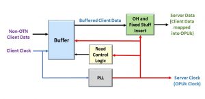
If the Client-data bit rate is slightly faster than that for the OPUk payload rate, then (with no intervention) the Mapper Buffer will eventually fill up.

AMP uses Negative-Stuffing (or Negative Justification) to prevent the Mapper buffer from Overflowing.  

In this case, the Source PTE will (temporarily) increase our Server (OPUk) signal’s bandwidth (to pull additional data out of the Mapper Buffer) by forcing both the PJO and the NJO bytes to carry client data momentarily.

Hence, for systems in which the Client data bit rate is faster than the OPUk payload bit rate, the Source PTE will periodically need to generate OPUk frames with Negative Justification to keep the Mapper Buffer from filling up.

Figure 4 shows a drawing of such an OPUk frame.

OPUk AMP Discussion - Negative Justification


Figure 4, Illustration of an OPUk Frame with Negative Justification occurring

This figure shows that this OPUk frame has a Negative Justification Event by setting at least two (of the three) sets of JC7 and JC8 bits to [0, 1], as I show above.  

The Source PTE will also (for this particular OPUk frame) use both the NJO and the PJO byte fields to carry client data bytes.

When the Source PTE sets the JC7 and JC8 bit-fields to these values, it notifies the Sink PTE (at the remote end of the network) of the roles of the NJO and PJO bytes within this OPUk frame.

NOTES:

  1. For the NO Justification OPUk frames, the NJO byte is considered part of the OPUk Overhead and usually does not transport any client data.  For Negative Justification OPUk frames, the NJO byte will (for this OPUk frame) be carrying client data.
  2. If the Client-data bit rate is faster than the OPUk Payload rate, then the PJO byte will ALWAYS carry client data (in every OPUk frame).  In this case, we will sometimes use the NJO byte to transport client data (within OPUk frames with justification events).

Positive Stuff Event (Occurs if the Client Bit Rate < OPUk Bit Rate)

If the Client-data bit-rate is slightly slower than that for the OPUk Payload rate, then (with no intervention) the Mapper Buffer will eventually be depleted.

AMP uses Positive-Stuffing (or Positive Justification) to avoid depleting the Mapper buffer.  

In this case, the Source PTE will temporarily reduce the Server signal’s (e.g., the OPUk signal) bandwidth (for this OPUk frame) by forcing both the PJO and the NJO bytes to transport stuff (and NOT client) data.

Hence, for designs in which the Client data bit rate is slower than the OPUk payload, the Source PTE will periodically generate OPUk frames with Positive Justification to avoid depleting the Mapper Buffer.

NOTE:  For the NO Justification OPUk Frames, the PJO byte field will be carrying client data.  But, during Positive Justification frames, the PJO byte will transport a stuff (or dummy) byte instead.  In other words, the Positive Justification OPUk frame will not carry client data within the PJO byte-field. 

This action momentarily slows the rate at which the Server pulls data out of the Mapper Buffer and keeps the buffer from depleting.

Figure 5 shows a drawing of an OPUk frame with Positive Justification occurring.

OPUK Frame - AMP Discussion - Positive Justification Frame


Figure 5, Illustration of an OPUk Frame with Positive Justification occurring

This figure shows that this OPUk frame has a Positive Justification event by setting at least two (of the three) sets of JC7 and JC8 bits to “[1, 1].

When the Source PTE sets the JC7 and JC8 bit-fields to these values, it notifies the Sink PTE (at the remote end of the network) of the roles of the NJO and PJO bytes within this OPUk frame.

NOTE:  If the Client data rate is slower than the OPUk Payload rate, then the NJO byte will ALWAYS function as a stuff byte (e.g., never carrying client data), and the PJO will sometimes function as a stuff byte (during OPUk frames with justification events).

Interpreting the JC7 and JC8 Bits

Table 1 summarizes how to understand the JC7 and JC8 bits (within two out of the three Justification Bytes) and the corresponding roles for the NJO and PJO bytes within the OPUk Frame.

Table 1, How to Interpret the Settings of the JC7 and JC8 bits within Two (of the Three) Justification Bytes, and the corresponding roles for the NJO and PJO bytes within the OPU Frame – When Transporting a Non-OTN Client Signal

Relationship between JC7 and JC8 bits and the Justification of OPUk

AMP and De-Mapping Jitter

AMP poses some challenges for the System Designer’s efforts to control de-mapping jitter to meet system requirements.  BMP offers the best de-mapping jitter of the three recommended Mapping Procedures.  

However, AMP imposes all of the following contributions (and challenges) to meeting de-mapping jitter requirements.

  • The presence of OTUk/ODUk/OPUk overhead bytes within the OTN signal (this challenge exists for BMP as well)
  • Fixed-byte stuffing – while mapping the client signal into the OPUk frame (this challenge exists for BMP as well)
  • Justification Events, also known as variable-stuffing, are unique to AMP.

Each Justification Event imposes 8UI-pp of mapping-related jitter within the client signal.

The System Designer will need to implement some clock-smoothing or jitter attenuation scheme to comply with de-mapping jitter requirements.

If the System Designer is transporting SONET/SDH data (which has very stringent jitter requirements) through the OTN, we recommend using BMP instead of AMP.  Otherwise, the designer will have to implement some very robust jitter attenuation solutions (at the Sink PTE) when de-mapping this client signal from the OPUk frame.

ITU-T G.709 Recommendations on Using AMP

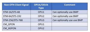
Table 2 presents a list of the Non-OTN Client signals that ITU-T G.709 recommends using AMP when mapping these signals into each OPUk/ODUk Structures.

Table 2, List of Client Signals that ITU-T G.709 Recommends using AMP when mapping into an OPUk Structure

ITU-T G.709 Recommendations for AMP - Asynchronous Mapping Procedure

Can we use AMP for all OPUk rates?

We can use AMP for the OPU1, OPU2, and OPU3 server signals.  However, we cannot use AMP for mapping client signals into an OPU0 or OPU4 server signal.

ITU-T G.709 recommends using GMP to map client signals into OPU0 and OPU4 signals.

Summary

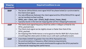
Table 3 summarizes the timing requirements (between the Client Clock Signal and that for the OPUk/ODUk clock) that the System Designer must follow before using any ITU-T G.709 Recommended Mapping Procedures.  Please note that I have highlighted the AMP items (within Table 3) with a “Red Rectangular” outline.

Table 3, Mapping Procedure Timing Requirements

ITU-T G.709 Requirements to use AMP - Asynchronous Mapping Procedure


Has Inflation got You Down? Our Price Discounts Can Help You Fight Inflation and Help You Become an Expert on OTN!! Click on the Banner Below to Learn More!!!

Discounts Available for a Short Time!!!

For More Information on OTN Posts in this Blog, click on the Image below.

OTN Related Blog

OTN Related Topics within this Blog

OTN Related Topics within this Blog General Topics Consequent Equations - What are they and How can you use them? ...

What is the PSI – Payload Structure Identifier Byte

This post describes the role of the PSI (Payload Structure Identifier) byte, within the OPUk Overhead, is used within the OTN.

What is the PSI – Payload Structure Identifier (Byte and Message)?

The PSI Byte

The PSI (or Payload Structure Identifier) byte is an Overhead byte within the OPUk structure.

Figure 1 presents an OPU frame with the location of the PSI byte identified.

Generic OPU Frame with PSI Byte Highlighted

Figure 1, Illustration of an OPUk Frame Structure with the Overhead Bytes (along with the PSI Byte) Identified  

The purpose of the PSI byte is to permit an OTN Path Terminating Equipment (PTE) to transport a 256-byte PSI (payload structure identifier) message throughout the OTN (Optical Transport Network).

The primary purpose of this 256-byte PSI Message is to permit the Source PTE to alert the OTN (Network) of the type of data (or traffic) we are transporting within this particular OPU data stream.

Since each OPUk frame contains only 1 PSI byte, an OTN PTE will have to transmit 256 consecutive OPU frames to transmit this PSI message completely.

The OTN PTE will align its transmission of this 256-byte PSI message with the MFAS byte.

Please see the OTUk Frame Structure post for more information on the MFAS byte.

In other words, whenever the OTN PTE is transmitting an OTUk frame with the MFAS byte set to “0x00”, then the OTN PTE will also be sending the first byte of the PSI message (e.g., PSI[0]) via the PSI byte-field.

Likewise, whenever the OTN PTE is transmitting an OTUk frame with the MFAS byte set to “0x01”, then the OTN PTE will also be sending the second byte within this 256-byte message (e.g., PSI[1]) via the PSI byte field, and so on.

Two Types of PSI Messages

An OTN Source PTE will transport one of two types of PSI Messages.

  • The Non-Multiplexed Traffic – PSI Message, and
  • The Multiplexed Traffic – PSI Message.

I will describe each of these types of PSI Messages below.  

The Non-Multiplexed Traffic PSI Message

We will use the Non-Multiplexed Traffic PSI Message when transporting Non-Multiplexed Traffic within our OPU data stream.

Examples of Non-Multiplexed Traffic would be:

  • Transporting 1000BASE-X via an OPU0 signal
  • 10GBASE-R via an OPU2e signal.
  • 100GBASE-R via an OPU4 Signal.

In other words, we are handling Non-Multiplexed Traffic whenever we only transport a single Non-OTN client signal via this OPUk data stream.  

I present an illustration of an OPU Frame, with the PSI field highlighted (along with a break-out of the Non-Multiplexed Traffic type of PSI Message) below in Figure 2.

OPU Frame with PSI Byte-Field highlighted and a Breakout of the Non-OTN Client/Non-Multiplexed PSI Message

Figure 2, Illustration of an OPU Frame, transporting the Non-Multiplexed traffic of PSI Message

NOTE:  The easiest way to tell if you’re working with the Non-Multiplexed Traffic type of PSI Message is to check and see if you see the CSF (Client Signal Fail) bit-field in PSI Byte # 2.

If the CSF bit-field is present, you’re dealing with the Non-Multiplexed Traffic type of PSI Message.

If the CSF bit-field is NOT present (within the PSI Message), then you are dealing with the other type of PSI Message.

The Multiplexed Traffic Type of PSI Message

We use the Multiplexed Traffic type of PSI Message anytime we work with an OPU server signal transporting numerous lower-speed ODUj Tributary Signals.

For example, if we mapped and multiplexed 80 ODU0 tributary signals into an OPU4 server signal, then this OPU4 signal would transport the Multiplexed Traffic type of PSI Message.

Figure 3 presents an illustration of an OPU Frame, with the PSI field highlighted, along with a break-out of the Multiplexed Type of PSI Message.

OPU Frame with PSI Byte-Field Highlighted and a Breakout of the Multiplexed Structure PSI Message

Figure 3, Illustration of an OPU Frame transporting the Multiplexed Traffic Type of PSI Message

Again, one big difference between the Multiplexed Traffic type of PSI Message and that for Non-Multiplexed Traffic is that the Multiplexed Traffic type of PSI Message will not have the CSF (Client Signal Fail) bit-field.

New Comprehensive OTN Training…Available Now. Click on the Banner Below to Learn More!!

Discounts Available for a Short Time!!!

The PSI Message

The PSI (Payload Structure Identifier) message is a 256-byte message that an OTN terminal will transport via the PSI byte for 256 consecutive OPUk/ODUk/OTUk frames.

Let’s talk a little bit about the data that we are transporting within these PSI Messages.  

PSI[0] – or PSI Byte # 0 – PT (Payload Type)

The first byte of the PSI Message (e.g., PSI[0]) carries the Payload Type (or PT) value.  The PT byte identifies the type of client data the OPUk structure is transporting via its payload.  

First, Table 1 presents a list of standard PT values and the corresponding client data types (being transported within the OPUk Structure).

Table 1a, PT (PSI[0]) Values, and the Corresponding Client Data within the OPUk Structure – Part I

PT - Payload Type - PSI Byte - Client Signal into OPUk

Table 1b, PT (PSI[0]) Values, and the Corresponding Client Data within the OPUk Structure – Part II

PT - Payload Type - PSI Byte - Client Signal into OPUk

NOTES: 

  1. We will discuss the PT = 0x07 case when mapping 100GBASE-R into an OPU4 in Lesson 4.  
  2. Access to Lesson 4 requires that you have a membership to “THE BEST DARN OTN TRAINING PERIOD” training.

Table 1c, PT (PSI[0]) Values, and the Corresponding Client Data within the OPUk Structure – Part III

PT - Payload Type - PSI Byte - Client Signal into OPUk

NOTE: 

  1. We will discuss cases where PT = 0x20 and 0x21 in Lesson 5.  
  2. Access to Lesson 5 requires that you have a membership to “THE BEST DARN OTN TRAINING PERIOD” training.

Table 1d, PT (PSI[0]) Values, and the Corresponding Client Data within the OPUk Structure – Part IV

PT - Payload Type - PSI Byte - Client Signal into OPUk

Other posts contain detailed information on how ITU-T G.709 recommends that the System Designer map each client signal into their corresponding OPUk structure.

Click HERE for more information about the PT = 0x21 Method for Mapping/Multiplexing Lower-Speed ODUj signals into a Higher-Speed ODUk Signal.

The Remaining Bytes within the PSI Message

PSI bytes 1 and 3 through 255 are for “Mapping and Concatenation Specific” roles that we will discuss in another post. 

In Multiplexed-Traffic Type of PSI Messages

For the Multiplexed-Traffic type of PSI Message, we use these bytes to transport MSI (Multiplex Structure Identifier) information throughout the OTN.  

In other words, we will transport the MSI information (via these PSI Messages) for applications in which we are mapping/multiplexing lower-speed ODUj tributary signals into higher-speed OPUk/ODUk server signals.

The MSI aims to identify these lower-speed ODUj tributary signals we are transporting via this OPUk/ODUk signal to the OTN.  

You can think of the MSI as a passenger list or manifest of lower-speed ODUj tributary signals riding along (or being transported) within this OPUk server signal.  

In Non-Multiplexed-Traffic Type of PSI Messages

PSI byte 2, Bit 1 (for the Non-Multiplexed Traffic PSI Message) is the CSF (or Client Signal Fail) indicator.  The ITU-T Standards Committee has reserved PSI Byte 2, Bits 2 through 8 for “future standardization.”

We discuss the CSF indicator and the MSI information in other posts.

We also extensively discuss these PSI Messages within THE BEST DARN OTN TRAINING PRESENTATION….PERIOD!!!.  

You can click on the Banner below to learn more our this training package.

Has Inflation got You Down? Our Price Discounts Can Help You Beat Inflation and Help You Become an Expert on OTN!!  Click on the Banner Below to Learn More.

Discounts Available for a Short Time ONLY!!

For More Information on OTN-Related Posts in this Blog, click on the image below.

OTN Related Blog

OTN Related Topics within this Blog

OTN Related Topics within this Blog General Topics Consequent Equations - What are they and How can you use them? ...

The BMP (Bit-Synchronous Mapping Procedure)

This post describes the Bit-Synchronous Mapping (BMP) for mapping non-OTN CBR client signals into an OTN signal.


What is the BMP (Bit-Synchronous Mapping Procedure)?

This post describes the BMP (Bit-Synchronous Mapping Procedure) for mapping a non-OTN CBR (Constant Bit Rate) client signal into an OPUk/ODUk signal.

NOTE:  Whenever ITU-T G.709 discusses procedures for mapping a client signal into an OPUk/ODUk signal, it will often refer to the OPUk/ODUk signal as the Server signal.  

Therefore, we will use the terms OPUk/ODUk and Server interchangeably throughout the remainder of this post.

ITU-T G.709 also defines two other mapping procedures that one can use to map a non-OTN CBR client signal into a Server signal.

(*) – Requires membership to THE BEST DARN OTN TRAINING PRESENTATION…PERIOD!!  to see this post.  

We discuss each of these other two mapping procedures in other posts.

What is the Bit-Synchronous Mapping Procedure?  

The name Bit-Synchronous Mapping Procedure means that there is a bit-synchronous relationship between the client signal (that we are mapping into an OPUk payload) and the bit rate of the OPUk payload.

In other words, the System Designer must ensure that ALL the following conditions are true before they can use the Bit-Synchronous Mapping Procedure to map a particular client signal into the OPUk payload.

  • The OPUk/ODUk/OTUk clock signal must be phase-locked (or synchronized) to the client clock signal, as Figure 1 illustrates below.

Timing Requirements between Client Signal and OPUk/ODUk Signal to use Bit Synchronous Mapping Procedure - BMP

Figure 1, Illustration of the Synchronization Requirements (between the OPUk/ODUk/OTUk signal and the client signal) to use BMP

  • We must use fixed-stuffing to handle rate differences (between the Client signal and OPUk/ODUk/OTUk signal).
    • In other words, we insert a fixed number of bits/bytes into the Server (OPUk) payload, along with the client data.
      • OPUk_rate = Client_rate + (Fixed_Stuff x Server_Frame_Rate);
  • Client bit-rate tolerances MUST NOT exceed the Server bit-rate tolerances.
    • For example, if the bit-rate tolerance for an OPUk is +/-20ppm, then the Client signal’s bit rate tolerance cannot exceed +/-20ppm.

New Comprehensive OTN Training…Available Now. Click on the Banner Below to Learn More!!!

Discounts Available for a Short Time!!

ITU-T G.709 Recommendations on Using BMP

ITU-T G.709 recommends using BMP when mapping the following non-OTN Client Signals into each of the OPUk/ODUk Structures listed below in Table 1.

Table 1, List of Client Signals that ITU-T G.709 Recommends using BMP when mapping into an OPUk Structure

ITU-T G.709 Recommendations for the Bit-Synchronous Mapping Procedure (BMP)

BMP and De-Mapping Jitter

BMP offers the best de-mapping jitter of the three recommended Mapping Procedures.  

Fixed stuffing and the presence of the OTUk/ODUk/OPUk overhead bytes are the only contributions to mapping (and de-mapping jitter).  Justification events (which imposes 8UI-pp of mapping-related jitter) for AMP applications do not occur in BMP.

However, the System Designer will still need to implement a clock-smoothing or jitter attenuation scheme to comply with de-mapping jitter requirements.  

This requirement is especially true for SONET/SDH applications.

Summary

Finally, Table 2 summarizes the timing requirements (between the Client Clock Signal and that for the OPUk/ODUk clock) that the System Designer must comply with before using any ITU-T G.709 Recommended Mapping Procedures.  

Please note that I have highlighted the BMP items below with a “Red Rectangular” outline.

TABLE 2, MAPPING PROCEDURE TIMING REQUIREMENTS

BMP Mapping Requirements

Has Inflation got You Down? Our Price Discounts Can Help You Fight Inflation and Help You Become an Expert on OTN!! Click on the Banner Below to Learn More!!!

Discounts Available for a Short Time!!!

For More Information on OTN Posts in this Blog, click on the Image below.

OTN Related Blog

OTN Related Topics within this Blog

OTN Related Topics within this Blog General Topics Consequent Equations - What are they and How can you use them? ...

ODU/ODUk – Optical Data Unit

This post defines and describes the ODU (Optical Data Unit) Frame that is used in OTN (Optical Transport Networks).

What is the ODU/ODUk (Optical Data Unit)?

An ODU (Optical Data Unit) is a data structure that Path Terminating Equipment (PTE)  within an Optical Transport Network (OTN) will generate and monitor as it transmits and receives data.

This post will call any entity that generates and transmits ODUk frames a Source PTE.  Likewise, we will call any entity that receives, processes, and terminates ODUk frames a Sink PTE.  

Anytime an OTN Terminal “wishes” to transport an ODUk frame to the outside world (over a fiber-optic connection), it will first encapsulate this data into an OTUk Frame.

In other words, an ODUk frame is a subset of an OTUk frame.

NOTE:  This post will discuss the ODUk structures (such as the ODU0, ODU1, ODU2, ODU2e, ODU3, ODU4, and ODUflex).

This post will not be discussing the new (higher-rate) ODUCn structures.  Please see the post on ODUCn structures for information on these types of structures.

OTN Path and Section Terminating Equipment

In the OTN arena, we will often state that the OTN Path Terminating Equipment (PTE) is the entity that is responsible for handling and processing ODUk frames.

We will also state that OTN Section Terminating Equipment (STE) handles and processes OTUk frames.

Please see the posts for OTN Path Terminating Equipment (PTE) and OTN Section Terminating Equipment (STE) to understand these two types of equipment.

The ODUk Frame Format

An ODUk consists of an OPUk structure, along with the ODUk Overhead fields.

Figure 1 presents an illustration of the ODUk structure, along with its overhead.

ODU Frame with ODU Overhead Shown

Figure 1, Illustration of an ODUk Structure

The ODU Structure (and Overhead) aims to help the OTN manage the transmission of OPU frames (transporting client data) from the Source PTE to the Sink PTE.

The OTN will use the ODU Overhead to monitor the Network’s performance and health (or the Path) as we transport these OPUk frames from the Source PTE to the Sink PTE.  

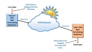
Figure 2 illustrates a single OTN Path network connection bounded by a Source PTE and a Sink PTE.

OTN Path Terminating Equipment connected to the Optical Transport Network

Figure 2, an Illustration of a single OTN Path (which is bounded by both a Source PTE and a Sink PTE)

The Source and Sink PTE (in Figure 2) will perform the following tasks on the data it processes.

Processing at the Source PTE

The Source PTE is a piece of equipment that will take on the responsibility of mapping a client signal into an OTN signal (e.g., into an OPUk structure).

Whenever the Source PTE maps this client signal (which could be a 1GbE, 100GbE, OC-48, FC-800 Signal, etc.) into an OTN signal:

  • It will accept the client data (from the client-side equipment), and it will map this signal into an OPUk Structure, and
  • The Source PTE will also compute and generate the ODUk Overhead, and
  • Finally, it will combine the ODUK Overhead and OPUk Structure to form an ODUk Frame.

Processing at the Sink PTE

The Sink PTE  will also be responsible for de-mapping (or extracting) the client signal from the OTN signal.

In this case, whenever the Sink PTE de-maps this client signal from an OTN signal:

  • It will evaluate the ODUk Overhead of each ODUk frame it receives (to check for client signal data integrity and the occurrence of defect conditions).  It will terminate the ODUk signal.
  • The Sink PTE will also terminate the OPUk structure and
  • It will de-map (or extract) the client signal from the OPUk structure.
  • Finally, the Sink PTE will output this client signal to the client-side equipment for further processing.

NOTE:  The OTN Path Terminating Equipment (at the “Source” and “Sink” terminals) will map (the client signal into an OTN signal) and de-map (the client from the OTN signal) in such a way as to minimize the amount of jitter within the de-mapped client signal.

Please see the posts on BMP, AMP, and GMP mapping for more details on this topic.

Things that the user can do with an ODUk frame

Once a “Source” PTE creates an ODUk frame, there are two things that it can do with the ODUk frames.

  • The Source PTE/STE can encapsulate this ODUk into an OTUk frame structure and then transmit this OTUk frame to a remote piece of terminal equipment (over a fiber-optic connection), or
  • It can treat this ODUk signal as a tributary signal and multiplex this ODUk signal into a higher-speed ODUm server signal (where m > k).  Please see the post on ODUk Multiplexing for more details.

You cannot transport an ODUk signal over optical fiber without first mapping this signal into an OTUk signal.  We only transport OTUk signals on optical fiber.  

Definition of the ODUk Overhead

The ODUk Overhead is a 3 Row by 14 Byte Column structure that contains the following thirteen (13) fields.

  • RES – Reserved
  • PM/TCM Byte
  • EXP – Experimental Byte
  • TCM1 Field
  • TCM2 Field
  • TCM3 Field
  • TCM4 Field
  • TCM5 Field
  • TCM6 Field
  • PM Field
  • GCC1 Field
  • GCC2 Field
  • APS/PCC Field

I describe each of these overhead fields below.

RES – Reserved

These fields are “reserved” and currently have no standardized role or function within the ODU overhead.

New Comprehensive OTN Training…Available Now. Click on the Banner Below to Learn More!!

Discounts Available for a Short Time!!

PM (Path Monitoring) Field (3 Bytes)

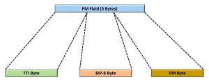
Figure 3 shows the byte format for the Path Monitoring Field.

ODU PM (Path Monitoring) Field

Figure 3, Byte-Format of the PM (Path Monitoring) Field.

Hence, Figure 3 shows that the PM Field consists of the following three bytes:

  • TTI- Trail Trace Identifier Byte
  • BIP-8 Byte
  • PM Byte

Below, we will describe each of the bytes (within the PM field).  We also discuss these bytes in much greater detail in other posts.

TTI Byte – Trail Trace Identifier Byte

This byte-field carries the 64-byte Path Monitoring Trail-Trace Identifier message.

Since there is only one TTI byte within each ODU frame (not including that within the TCMn fields), the Source PTE will have to transmit 64 consecutive ODUk frames to transmit this 64-byte Trail Trace Identifier message completely.

Please see the Path Monitor – Trail Trace Identifier post to see how we use this identifier in an OTN system.

BIP-8 (Path Monitoring, BIP-8) Byte

The PTE will perform a BIP-8 calculation over the entire OPUk frame within its corresponding ODUk frame.

Afterward, the Source PTE will insert the results of this BIP-8 calculation into the BIP-8 byte field of the outbound ODUk frame two frame periods later.

The remote Sink PTE will use this BIP-8 calculation to check for bit errors during transmission from the Source PTE to the Sink PTE.

Please see the Path Monitoring BIP-8 post for more information about this byte field and how it is computed and used in an OTN system.

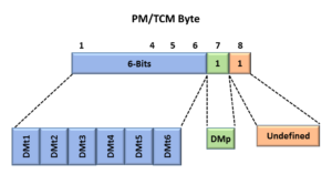
PM (Path Monitoring) Byte

Figure 4 presents the bit format for the Path Monitoring byte (not to be confused with the 3-byte PM Field).

ODU PM (Path Monitoring) Byte - BEI, BDI, STAT

Figure 4, Bit Format of the Path Monitoring Byte

This figure shows that the PM Byte consists of the following bit-fields

  • BEI (4-bits)
  • BDI (1 bit)
  • STAT (3 bits)

We will briefly describe each of these bit-fields below.

BEI – Path Monitoring – Backward Error Indicator (BEI) (4 bits)

The purpose of the BEI Nibble field is to permit a Network Element (consisting of a Source PTE and a Near-End Sink PTE) to send feedback to the far-end Network Element on the quality of the ODUk signal that it is sending to our Network Element.

As the Near-End Sink PTE receives its stream of ODUk frames (from the far-end Network Element), it will check and verify the PM-BIP-8 values within each incoming ODUk frame.  

While the Near-End Sink PTE performs this task, it will determine the total number of bits in error between its locally computed PM-BIP-8 byte value and that it has received from the far-end Network Element.  

The Source PTE will obtain that number from its Near-End Sink PTE and then load that number (of PM-BIP-8 bits in error) into the BEI Nibble-field within the ODUk frames and transmits it back out to the far-end Network Element.  

In doing this, our local Network Element provides the far-end Network Element with the total number of PM-BIP-8 bit errors that are received from it.

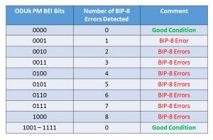
Table 1 lists the value that our Near-End Source PTE will set the BEI Nibble based upon the number of PM-BIP-8 bit errors that its Near-End Sink PTE has detected.  

Table 1, How to Interpret the Path Monitoring BEI bit-fields

ODUk PM BEI Bits and the Number of BIP-8 Errors Detected

Please see the Path Monitoring Error/Defect post to learn more about these defects and error conditions.

BDI – Path Monitoring – Backward Defect Indicator

The purpose of the BDI bit-field is to permit the Source PTE to alert the remote (far-end) Network Element that the local (near-end) Sink PTE is declaring a service-affecting defect.  

The Source PTE will set this bit-field to a “0” or “1” depending upon whether the local (near-end) Sink PTE is declaring a service-affecting defect condition (at the ODUk-layer), as I describe below. 

0 – The Source PTE will set the BDI bit-field to “0” if the near-end Sink PTE is NOT declaring a service-affecting defect condition.

1 – The Source PTE will set this bit-field to “1” if the near-end Sink PTE is currently declaring a service-affecting defect condition.

Please see the Path Monitoring Error/Defect post to learn more about the BDI defect.

STAT – ODU Path Monitoring Status (STAT) Indicator

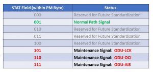
The Sink PTE will use the STAT fields to determine if it should declare a Maintenance signal-related defect, as shown below in Table 2.

Table 2, How to Interpret the STAT bit-fields within the PM Field

STAT Field within the Path Monitor Field of an ODU Frame

For example, if the Sink PTE were to receive (and accept) a STAT field value of [1, 0, 1], then the Sink PTE will declare the dAIS (ODUk-AIS) defect condition.  

PM/TCM Byte

For ODUk applications (e.g., ODU0, ODU1, ODU2, ODU3, ODU4, and ODUflex), the PM/TCM byte contains seven (7) defined bit-fields.

Figure 5 presents an illustration of the PM/TCM Byte-field.

Path Montoring/Tandem Connection Monitor Byte

Figure 5, Illustration of the PM/TCM Byte-Field

This figure shows that Bit 7 (within the PM/TCM Byte-Field) functions as DMp (or Path Delay Measurement) and that bits 1 through 6 functions as DMti (of Tandem Connection Monitoring Delay Measurements).

Please see the DMp (Path Delay Measurement) post for more details on the DMp bit-field.  And please see the post on DMt1 through DMt6 (TCM Delay Measurements) for more information about the DMti bit-fields.

EXP – Experimental Byte (4 Bytes within the ODUk Overhead)

The ODU Overhead has a total of 4-byte fields that are labeled EXP.  There are two (2) 1-byte fields and one (1) 2-byte field for EXP.

There is no standard-specified use for the EXP bytes.

For now, the System Designer/Manufacturer can use these byte fields to support vendor-proprietary features if they choose to do so.

New Comprehensive OTN Training…Available Now. Click on the Banner Below to Learn More!!

Discounts Available for a Short Time!!

TCM1 (Tandem-Connection Monitoring 1) Field

TCM1 through TCM6 all support Tandem Connection Monitoring.

Please see the post on Tandem Connection Monitoring for more information on how these fields are used in the OTN.

The byte field for the TCM1 field is presented and briefly defined below.  See Figure 6 for the byte format of the TCM1 field.

TCMi (Tandem Connection Monitoring) Field

Figure 6, Byte-Format of the TCM1 Field

Figure 6 shows that the TCM1 Field consists of the following three bytes:

  • TTI- Trail Trace Identifier Byte
  • BIP-8 Byte
  • TCMi-SM Byte

NOTES

  1. The role of the TTI and BIP-8 bytes within the TCM1 field is identical to that presented for the ODUk Path Monitoring Field, and we will not repeat that discussion here.  Please see the post on Tandem Connection Monitoring for more details on how the OTN network uses these byte fields.
  2. Note that the TCMi-SM byte is different from the ODUk PM byte.  Please see the post on the TCMi-SM byte for more information on how we use this byte-field in the network.
  3. The role of the bytes within the TCM1 field is identical to that for the TCM2 through TCM6 fields, and we will not repeat that discussion below.  Please see the post on Tandem Connection Monitoring for more details on how the OTN network uses these byte fields.

TCM2 Field

Please see the description for the TCM1 Field.

TCM3 Field

Same as the description for the TCM1 Field.

TCM4 Field 

Please see the description for the TCM1 Field.

TCM5 Field

Same as the description for the TCM1 Field.

TCM6 Field

Please see the description for the TCM1 Field.

GCC1 – General Communication Channel # 1 – (2 byte)

The GCC1 field is a general communications channel for proprietary communication to the System Designer/Manufacturer.

This channel is similar to the DCC (Data Communication Channels) in SONET/SDH.

Please see the GCC1 post for more information about this field.

GCC2 Field – General Communication Channel # 2 – (2 Byte)

The GCC2 is a general communications channel for proprietary communication to the System Designer/Manufacturer.

This channel is similar to the DCC (Data Communication Channels) in SONET/SDH.

Please see the GCC2 post for more information about this field.

APS/PCC Field – ODU Automatic Protection Switching and Protection Communication Channel

Please see the ODU Automatic Protection Switching and the Protection Communications Channel post to learn more about how we use this 4-byte field in an OTN system.

ODUk Bit Rates

Table 3 presents the ODUk bit rate for each type of ODUk signal.

Table 3, Bit-Rate for each type of ODUk Signal

ODUk Bit Rate

NOTES:

  1. We define the ODUflex structure in another post.
  2. This post only addresses ODUk types of structures.  Please see the post on ODUCn to learn more about those structures.

Has Inflation got You Down? Our Price Discounts Can Help You Fight Inflation and Help You Become an Expert on OTN!! Click on the Banner Below to Learn More!!!

Discounts Available Temporarily

For More Information on OTN Posts in this Blog, click on the Image below.

OTN Related Blog

OTN Related Topics within this Blog

OTN Related Topics within this Blog General Topics Consequent Equations - What are they and How can you use them? ...

The OTU (Optical Transport Unit) Frame

This post defines and describes the OTU (Optical Transport Unit) Frame that is used in OTN (Optical Transport Networks).

What is the OTU Frame/OTUk Frame?

An OTU (Optical Transport Unit) frame is a data structure that an OTN Terminal (or Source STE) will use to transport its data to the outside world.

This post will call any entity that generates and transmits OTUk frames a Source STE (Section Terminating Equipment).  Likewise, we will call any entity that receives, processes, and terminates OTUk frames a Sink STE.  

In other words, as the Source STE accepts OPU/ODU frames to create an OTUk frame, it will encapsulate these OPU/ODU frames into an OTU frame by “tacking” on the OTUk overhead. 

Additionally, the Source STE will pre-condition each OTUk frame for transport over Optical Fiber by computing and appending an FEC (Forward Error Correction) field at the back end of the OTU frame and scrambling much of the OTUk frame data before converting this data into the optical domain and sending it out on Optical Fiber.  

Likewise, the OTU frame is a data structure that an OTN Terminal (or Sink STE) will accept as it receives data from the outside world.

In this case, the OTN Terminal (e.g., Sink STE) will perform the reverse functions as the Source STE.  

It will receive an optical signal from the remote STE and convert this data back into an electrical format.  Afterward, it will descramble this incoming OTUk data stream, decode the FEC field, and correct most symbol errors in the process.  

Finally, the Sink STE will terminate the OTUk data stream by extracting out the OPU/ODU frames and routing this data to downstream circuitry.  

To be clear, What do We Mean by Frame?

OTN, just like many other Networking Standards, uses framing to organize the data it transmits and receives.

Framing is a Data Link Layer function.  A transmitting terminal will organize a group of data bits into a specific data structure (called a “frame”) before transmitting it across a link.

Please see the post about the Data Link Layer for more information about the concept of Framing.

Please note that we are not talking about this kind of frame.

For OTN applications, we only transmit data that we have encapsulated into the form of an OTU frame out onto optical fiber.

OPUk and ODUk signals may be handled and processed internally (within a network element or an integrated circuit).

But we NEVER transmit OPUk and ODUk data onto the network (over optical fiber) unless we first encapsulate these signals into an OTUk frame and pre-condition this data for transport over Optical Fiber.

OTN Section and Path Terminating Equipment

In the OTN arena, we will often state that OTN Section Terminating Equipment (STE) is the entity that is responsible for transmitting and receiving OTUk frames.

We will also state that OTN Path Terminating Equipment (PTE) handles and processes ODUk frames.

Please see the posts for OTN Section Terminating Equipment (STE)and OTN Path Terminating Equipment (PTE) to understand the differences between these two types of equipment.

The OTUk Frame Format

Figure 1 illustrates the format for the standard ITU-T G.709-compliant OTU Frame.

OTUk Frame - Byte Format

Figure 1, Illustration of the Format of the ITU-T G.709-Compliant OTU Frame

This figure shows that an OTU Frame is a 4-Byte-Row by 4080-Byte-Column Structure.  Hence, each OTU Frame consists of (4 x 4080 =)16,320 bytes.

Please note that all OTU Frames (whether an OTU1, OTU2, OTU3, or OTU4 frame) are all the same size; therefore, each frame has exactly 16,320 bytes.

NOTE:  Since each of these OTU frames are the same size (regardless of whether we are talking about an OTU1, OTU2, OTU3, or OTU4), we will, from here on, refer to these OTU frames as OTUk frames.

The Fields within an OTUk Frame

Let’s talk about the various fields within an OTUk frame.

Some of the fields in the OTUk frame have the following labels.

  • FAS
  • MFAS
  • OTUk OH
  • FEC
  • ODUk Frame

I will briefly define each of these bytes below.

FAS – Framing Alignment Signal field

The Framing Alignment Signal field occupies the first 6 bytes within an OTUk Frame.

The first three bytes (which we sometimes call the OA1 bytes) each have a fixed value of 0xF6.

The remaining three bytes (in the FAS field), which we sometimes call the OA2 bytes, each have a fixed value of 0x28.

The purpose of the FAS bytes is to provide the remote receiving OTN terminal (e.g., the Sink STE) with this fixed pattern so that it will “know” that it is receiving the first bytes of a new OTUk frame.

The Sink STE will parse through its incoming OTUk frame data stream.  As it does this, it will search for the occurrence of three consecutive bytes (each with the value 0xF6) followed by another set of three successive bytes (each with the value 0x28).

The Sink STE will rely on these FAS bytes to acquire and maintain framing alignment/synchronization with the incoming stream of OTUk frames.

If the Sink STE repeatedly fails to acquire and maintain framing alignment/synchronization with this incoming stream of OTUk frames, it will declare the dLOF (Loss of Frame) defect condition.  

MFAS – Multi-Frame Alignment Signal byte

The MFAS byte occupies the 7th byte within an OTUk frame and “resides” immediately after the FAS bytes.

Unlike the FAS bytes, the MFAS byte’s value is not fixed, as I will explain here.  

A given Source STE will transmit OTUk frames in groups of Multi-frames.

Each of these multi-frames consists of 256 consecutive OTUk frames.

Whenever a Source STE transmits the first OTUk frame (of a given Multi-frame), it will designate this particular frame as the first frame (of this multi-frame) by setting its MFAS byte field to 0x00.

When the Source STE transmits the next OTUk frame, it will set the MFAS byte (within that particular OTUk frame) to 0x01, and so on.

As the Source STE transmits each OTUk frame, it will increment the value assigned to the MFAS byte field until it reaches the value 0xFF (or 255 in decimal format).

The Source STE will then start over with transmitting a new multi-frame and set the MFAS of this next OTUk frame to 0x00, and the process repeats indefinitely.

The MFAS is a significant byte for a receiving OTN terminal (e.g., Sink STE) to keep track of because other data (such as the TTI – Trail Trace Identifier message – that is transmitted via some of the additional overhead bytes across multiple OTUk frames).

The Source STE will align the transmission of these particular messages (e.g., the SM-TTI messages, PM-TTI messages, PSI Messages, etc.) with the MFAS byte as it transports these messages via the OTUk data stream.

Please see the relevant posts on SM-TTI (Section Monitoring – Trail Trace Identifier) Messages, PM-TTI (Path Monitoring – Trail Trace Identifier) Messages, and PSI (Payload Structure Identifier) Messages to learn more about these types of messages.  

ODUk Frame

The ODUk Frame “portion” of the OTUk frame is all the remaining data (which resides within the OTUk frame) that is not considered an OTUk Overhead field.  This includes all bytes within the ODU (Optical Data Unit) and, in turn, OPU (Optical Payload Unit) within the OTUk frame.  Please see the posts for ODUk and OPUk to learn more about those parts of the OTUk frame.

FEC – Forward Error Correction

ITU-T G.709 specifies that OTUk frames should include an FEC (Forward Error Correction) field that contains the Reed-Solomon RS (255,239) FEC codes.

NOTE:  I discuss the RS(255,239) FEC code in detail in Lesson 9, within THE BEST DARN OTN TRAINING PRESENTATION…PERIOD!!!

The FEC field permits a Sink STE to detect and correct many symbol (or byte) errors that may have occurred during transmission.

ITU-T G.709 indicates that using FEC is optional for OTU1, OTU2, and OTU3 applications.  

However, the use of FEC is mandatory for OTU4 applications.  

Please see the OTUk FEC discussion within Lesson 9 of THE BEST DARN OTN TRAINING PRESENTATION…PERIOD!!  for more information about this field.

New Comprehensive OTN Training…Available Now. Click on the Banner Below to Learn More!!!

Discounts Available for a Short Time!!!

The Rest of OTUk OH (Overhead) fields

The remaining OTUk OH fields consist of the following three fields for a total of seven (7) bytes:

  • SM Field
  • GCC0 Field
  • OSMC (OTN Synchronizing Messaging Channel) Field
  • RES (Reserved) Field

We will briefly describe each of these fields below.

SM (Section Monitoring) Field (3 bytes)

Figure 2 shows the byte format for the Section Monitoring or SM Field.

OTU - SM (Section Monitoring) Field, TTI Byte, BIP-8 Byte, SM Byte

Figure 2, Byte-Format of the SM (Section Monitoring) Field

This figure shows that the SM Field consists of the following three bytes:

  • TTI – Trail Trace Identifier Byte
  • BIP-8 Byte
  • SM Byte

Below, we will describe each of the bytes (within the SM field).  We also discuss these fields in much greater detail in their respective posts.

TTI – Trail Trace Identifier Byte

This byte-field carries the 64-byte Section Monitoring Trail-Trace Identifier message.  Since there is only one TTI byte within each OTUk frame, the OTN Transmitter (or Source STE) will transmit 64 OTUk frames to send the entire 64-byte Trail Trace Identifier message.

Please see the Section Monitor-Trail Trace Identifier post to learn how we use this identifier in an OTN system.

BIP-8 (Section Monitoring BIP-8) Byte

The Source STE will perform a BIP-8 calculation over the entire OPUk frame within its corresponding OTUk frame.

Afterward, the Source STE will insert the results of this BIP-8 calculation into the SM-BIP-8 byte field of the outbound OTUk frame two frame periods later.

Finally, the remote Sink STE will use this BIP-8 calculation to check for bit errors during transmission.

Please see the Section Monitoring BIP-8 post for more information about how we compute and use this byte field in an OTN system.

SM (Section Monitoring) Byte

Figure 3 presents the bit format for the Section Monitoring Byte (not to be confused with the 3-byte SM field).

OTU Frame - Section Monitoring Byte Format - Optical Transport Networks

Figure 3, Bit Format of the Section Monitoring Byte

This figure shows that the SM Byte consists of the following bit fields:

  • BEI/BIAE (4 bits)
  • BDI (1 bit)
  • IAE (1 bit)
  • RES – Reserved (2 bits)

We will briefly describe each of these bit-fields below.

BEI/BIAE – Section Monitoring – Backward Error Indicator (BEI) or Backward Incoming Alignment Error (BIAE) – (4 bits)

The purpose of the BEI/BIAE nibble-field is two-fold.

  • To permit the Source STE to provide the remote Sink STE (at the far-end) with feedback on the number of SM-BIP-8 errors that the near-end (local) Sink STE is detecting within its incoming OTUk data stream.
    • The Source STE will set the BEI/BIAE nibble-field (within each outbound OTUk frame) to the SM-BEI (Backward Error Indicator) value.  
  • And to permit the Source STE to alert the remote Sink STE (again, at the far-end) that the near-end (local) Sink STE is declaring the dIAE defect condition.
    • The Source STE will accomplish this by setting the BEI/BIAE nibble-field to the value of “1011”, which carries the BIAE (Backward Input Alignment Error) Indicator.  

Table 1 presents the range of values that the Source STE can set the BEI/BIAE Nibble-field, within its outbound OTUk frames, for each of the conditions mentioned above. 

Table 1, How to Interpret the Section Monitoring BEI/BIAE bit-fields

OTUk SM_BEI/BIAE Nibble-ValueSink STE declaring the dIAE Defect?Number of SM-BIP-8 Errors DetectedComments
0000NO0Good Condition
0001NO1BIP-8 Error
0010NO2BIP-8 Errors
0011NO3BIP-8 Errors
0100NO4BIP-8 Errors
0101NO5BIP-8 Errors
0110NO6BIP-8 Errors
0111NO7BIP-8 Errors
1000NO8BIP-8 Errors
1001, 1010NO0Good Condition
1011YES0BIAE Indicator
1100 to 1111NO0Good Condition

Please see the Section Monitoring Error/Defect post to learn more about these defect and error conditions.

BDI – Section Monitoring – Backward Defect Indicator Bit Field

The purpose of the BDI bit-field is to permit the Source STE to alert the remote (far-end) Network Element that the local (near-end) Sink STE is declaring a service-affecting defect.  

This Source STE will set this bit-field to “0” or “1” depending upon whether the local (near-end) Sink STE is declaring a service-affecting defect condition (at the OTUk-layer), as I describe below.

0 – The Source STE will set the BDI bit-field to “0” if the near-end Sink STE is NOT declaring a service-affecting defect condition.

1 – The Source STE will set the BDI bit-field to “1” if the near-end Sink STE is currently declaring a service-affecting defect condition.

Please see the OTUk-BDI post to learn more about the BDI defect condition.

IAE – Section Monitoring Incoming Alignment Error Bit-Field

The Source STE will set this bit-field to “0” or “1” depending upon whether the upstream circuitry detects a frame-slip event within an ODU signal that we are ultimately mapping into this particular OTUk data stream (that this Source STE is transmitting downstream).

0 – Indicates that upstream circuitry is NOT detecting any frame-slip events (within the ODU signal we are mapping into this particular OTUk signal).   The Source STE will set the IAE bit-field to “0” (within its outbound OTU data-stream) to denote this good condition.

1 – Indicates that upstream circuitry is currently detecting a frame-slip event (within the ODU signal we are mapping into this particular OTUk signal).  The Source STE will set the IAE bit-field to “1” (within its outbound OTU data-stream) to denote this abnormal condition.

I present detailed information on the IAE bit-field within Lesson 9 of THE BEST DARN OTN TRAINING PRESENTATION…PERIOD!!.

GCC0 – General Communication Channel # 0 – (2 bytes)

The GCC0 is a general communications channel for proprietary communication to the System Designer/Manufacturer.

This channel is similar to the DCC (Data Communication Channels) in SONET/SDH.

Please see the GCC0 post for more information about how the System Designer/Manufacturer can use this field.

OSMC – OTN Synchronization Messaging Channel  – 1 byte

The Network User can use the OSMC channel to transport SSM (Synchronization Status Messages) or PTP (Precision Time Protocol) messages throughout the OTN.

Please see the OSMC post for more information about how the System Designer/Manufacturer can use this field.

RES – Reserved (or Undefined) (1 byte)

OTUk Frame Repetition Rates and Bit Rates

Since all speeds (or types) of OTUk signals use the same frame size, the reason that (for example) an OTU2 runs at a faster bit rate than does an OTU1 is that the frame repetition rate for an OTU2 is higher (e.g., more rapid) than that for an OTU1.

Table 2 presents the OTUk frame period and bit rate for each type of the OTUk signal.

Table 2, Frame Periods and Bit-Rate for each kind of OTUk signal

OTUk Bit Rate and OTUk Frame Period

NOTES:

  1. This post has defined the Fully Compliant OTUk frames.   It does not address the functionally standardized OTUk frames (such as the OTUkV or OTUk-v).  Please see the posts for the OTUkV and OTUk-v frames for more information on these types of frames.
  2. This post does not discuss the new OTUCn types of OTN signals.  Please see the OTUCn post for more information on these higher-speed signals.

Has Inflation got You Down? Our Price Discounts Can Help You Fight Inflation and Help You Become an Expert on OTN!! Click on the Banner Below to Learn More!!

(DISCOUNT OFFERED for a Short Time ONLY!!)

For More Information on OTN Posts in this Blog, click on the Image below.

OTN Related Blog

OTN Related Topics within this Blog

OTN Related Topics within this Blog General Topics Consequent Equations - What are they and How can you use them? ...

What is the OPU – Optical Payload Unit?

This post presents the definition of an OPU (Optical Payload Unit) frame, within an OTU Frame.

What is the OPU – Optical Payload Unit?

The OPU (Optical Payload Unit) is that portion of an OTU Frame that transports “payload” or “client-data” throughout the Optical Transport Network.

An OPU is a subset of an ODU (Optical Data Unit) and an OTU (Optical Transport Unit) Frame.

Figure 1 presents an illustration of an OTU Frame and also identifies the location of the OPU frame.

OPUk Frame - Byte Format

Figure 1, Illustration of an OTU Frame with the OPU Portion (of the Frame) identified.  

We will typically give the OPU (just like its larger OTU cousin) a designation such as OPU0, OPU1, OPU2, OPU3, and OPU4, depending upon the “data rate” or the Data Carrying Capacity of this structure.

Table 1 lists the data-carrying capacity for each type of OPU structure.

Table 1, The Data Carrying (Rate) or Capacity of each OPU Structure.

OPUk Bit Rates, OPU0, OPU1, OPU2, OPU2e, OPU3, OPU4, OPUC4

From this point forward, we will refer to the OPU structure as an OPUk (where k can be 0, 1, 2, etc… as presented in Table 1).

NOTE:  We describe the ODUflex/OPUflex structure in another post.

The Basic OPUk Frame Format

The OPUk frame consists of two types of bytes:

  • Payload Bytes (which we use to transport the Client Data) and
  • Overhead Bytes permit OTN equipment to manage the transport of this data.

ITU-T G.709 typically draws the OPUk Payload as a 4-Row x 3808-Byte-Column Structure, yielding 15,232 bytes.

The OPUk Structure also includes 8 Overhead Bytes as well.  Hence, the full OPUk Frame (of OPU Payload and Overhead) is a 4-Row x 3810-Byte Column Structure, yielding 15,240 bytes.

Figure 2 presents a Generic Illustration of the OPUk Framing Format with the OPUk Overhead Bytes highlighted.

Generic OPUk Frame

Figure 2, Illustration of a Generic View of the OPUk Structure (e.g., OPUk Payload with the Overhead Bytes highlighted)

Why Do I Call Figure 2 a “Generic Illustration”?

I refer to Figure 2 as a “Generic Illustration” of the OPUk Structure because it includes all possible names/roles for the OPU Overhead bytes.

The names and roles of these OPUk Overhead fields will change depending on which of the following sets of data rates and mapping procedures we are using.

  • When operating at the OPU0 through OPU3 rates and using AMP/BMP Mapping
  • For the OPU0 through OPU3 rates and using GMP Mapping and
  • If running at the OPU4 rate and using GMP Mapping to map/de-map Non-OTN Clients
  • For the OPU4 rate and using GMP Mapping to map/de-map lower-speed ODUj tributary signals into/from this OPU4 server signal.

We will briefly illustrate and describe the roles of the OPUk overhead for each of these operating modes.

New Comprehensive OTN Training…Available Now. Click on the Banner Below to Learn More!!!

Discounts Available for a Short Time!!!

The OPUk Frame Format and Overhead for the OPU0 through OPU3 server rates when using BMP/AMP.

If we are supporting the OPU0 through OPU3 rates and if we are using AMP (Asynchronous Mapping Procedure) or BMP (Bit Synchronous Mapping Procedure) to map non-OTN client data or lower-speed ODUj tributary signals into this OPUk server signal, then Figure 3 shows us the OPUk Frame format and overhead that we will be using.

OPU0 through OPU3 AMP Applications

Figure 3, An Illustration of the OPUk Frame Format (and Overhead) for the OPU0 through OPU3 server rates whenever we use AMP or BMP.  

Figure 3 shows that the OPUk Frame (for this Operating Mode) has the following overhead bytes:

  • JC1 – Justification Control Byte # 1
  • JC2 – Justification Control Byte # 2
  • JC3 – Justification Control Byte # 3
  • PSI – Payload Structure Identifier Byte
  • NJO – Negative Justification Opportunity Byte
  • PJO – Positive Justification Opportunity Byte

In the case of the OPU0 – OPU3/AMP/BMP modes, the JC1, JC2, JC3, NJO, and PJO bytes will all support the mapping and de-mapping operations of client data into and out of the OPUk signal.

Please see the AMP Post for more details on the roles of these overhead byte fields.

The PSI byte carries information about and identifies the type of client data that the OPUk frame is transporting.

Please see the PSI post for more details about the roles of this byte-field.

NOTE:  Figure 3 presents the appropriate OPUk Frame Format and Overhead for all PT = 0x20 applications and some PT = 0x21 applications in which we use AMP.  

The OPUk Overhead for the OPU0 through OPU3 rates, when we use GMP to map/de-map client signals into/out of the OPUk server signal.

If we support the OPU0 through OPU3 rates and use GMP (the Generic Mapping Procedure) to map either non-OTN client data or lower speed ODUj tributary signals into this OPUk server signal then Figure 4 shows a drawing of the OPUk frame format that we will be using.

OPU0 through OPU3 - GMP Applications

Figure 4, An Illustration of the OPUk Frame Format for the OPU0 through OPU3 rates whenever we use the GMP mapping procedure.  

Figure 4 shows that the OPUk Frame (for this Operating Mode) has the following overhead bytes:

  • JC1 – Justification Control Byte # 1
  • JC2 – Justification Control Byte # 2
  • JC3 – Justification Control Byte # 3
  • JC4 – Justification Control Byte # 4
  • JC5 – Justification Control Byte # 5
  • JC6 – Justification Control Byte # 6
  • PSI – Payload Structure Identifier byte

In the case of the OPU0 – OPU3/GMP modes, the JC1, JC2, JC3, JC4, JC5, and JC6 bytes will all support the GMP mapping and de-mapping of client data into/from an OPUk signal.

Please see the GMP Procedure for Mapping/De-Mapping Non-OTN Client signal training (in Lesson 4 of THE BEST DARN OTN TRAINING PRESENTATION…PERIOD!!!) on how we use these byte-fields to support the mapping/de-mapping of non-OTN client data into/from OPU frames.

Likewise, please see Lesson 5 (within THE BEST DARN OTN TRAINING PRESENTATION…PERIOD!!!) for information on how we use the GMP Procedure for Mapping/De-Mapping Lower-Speed ODUj Tributary Signals into an ODUk Server signal.  This same lesson will also include information on how we use these byte-fields to support the mapping/de-mapping lower-speed ODUj tributary signals into/from the ODUk server signal.  

Once again, the PSI byte carries information about and identifies the type of client data that the OPUk frame is transporting.

Please see the PSI post for more details about the roles of this byte-field.

NOTE:  Figure 4 presents the appropriate OPUk Frame Format and Overhead for some PT = 0x21 applications.

The OPUk Overhead for OPU4 Applications – Non-OTN Client Case

If we support the OPU4 rate and use GMP to map/de-map a non-OTN client signal into/from this OPU4 signal, then Figure 5 presents an appropriate OPU4 frame format and overhead fields that we will be using.  Hence, we would use this OPU frame when GMP mapping a 100GBASE-R signal into an OPU4 signal.  

OPU4 Frame for Non-OTN Client applications

Figure 5, An Illustration of the OPU4 Frame structure whenever we use GMP to map/de-map a non-OTN client.  

Figure 5 is very similar to Figure 4, with one exception.

For OPU4 applications, the last eight columns (within the payload) are always a fixed-stuff region that we cannot use to transport data.

Other than that, Figure 5 has the same set of Overhead Bytes as does Figure 4.

The JC1, JC2, JC3, JC4, JC5, and JC6 bytes will all support the GMP mapping and de-mapping client data into/from an OPU4 signal.

Please see the GMP Procedure for Mapping/De-Mapping Non-OTN Client signals lesson (e.g., Lesson 4 within THE BEST DARN OTN TRAINING PRESENTATION…PERIOD!!!)  for more information on how we use these byte-fields to support the mapping/de-mapping of non-OTN client data.

The OPUk Overhead for OPU4 Applications – Lower-Speed ODUj Tributary Signal Case

If we are supporting the OPU4 rate and if we are also using GMP to map/de-map lower-speed ODUj tributary signals into/from this OPU4 server signal, then Figure 6 presents a drawing of the appropriate OPU4 frame format and overhead fields that we will be using.

OMFI Location

Figure 6, An Illustration of the OPU4 Frame structure whenever we use GMP to map/de-map lower-speed ODUj tributary signals.

Figure 6 is identical to Figure 5, with one exception.

For Non-OTN Client applications, the byte-field in Row 4/Column 16 is labeled “RES” (for RESERVED) and serves no purpose for mapping/de-mapping client data into/from the OPU4 signal.

For Lower-Speed ODUj Tributary Signal Mapping applications, we call this byte-field the OMFI (OPU Multi-Frame Identifier) field.

The JC1, JC2, JC3, JC4, JC5, JC6, and OMFI bytes will all support the GMP mapping and de-mapping of lower-speed ODUj tributary signals into/from an OPU4 signal.

Please see Lesson 5 within THE BEST DARN OTN TRAINING PRESENTATION…PERIOD!!!  For more information on how we use these byte-fields to support the mapping/de-mapping of Lower-Speed ODUj Tributary signals into an ODUk Server signal.

Has Inflation got You Down? Our Price Discounts Can Help You Fight Inflation and Become an Expert in OTN? Click Below to Learn More!!

Discounts Available Temporarily

For More Information on OTN Posts in this Blog, click on the image below.

OTN Related Blog

OTN Related Topics within this Blog

OTN Related Topics within this Blog General Topics Consequent Equations - What are they and How can you use them? ...